
Tolerances Engineering Drawing
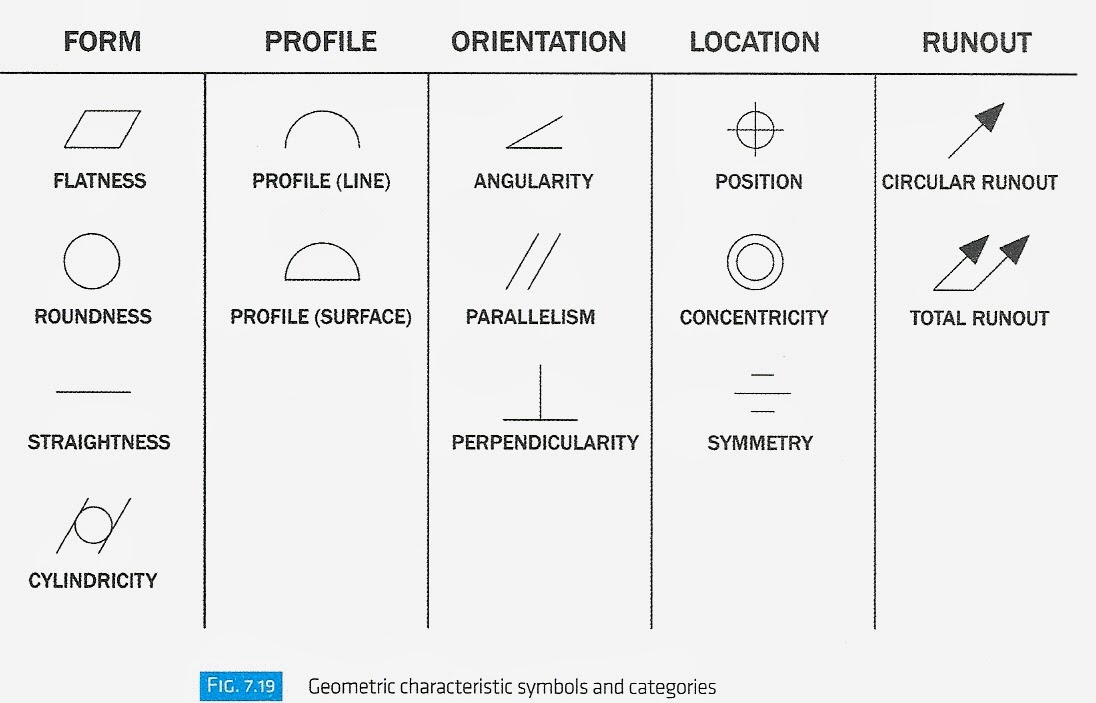
Tolerances Engineering Drawing - Gd&t, short for geometric dimensioning and tolerancing, is a system for defining and communicating design intent and engineering tolerances that helps engineers and manufacturers optimally control variations in manufacturing processes. Adding a lower deviation tells the manufacturer how much smaller a certain measurement can be. The three main categories are: A fully defined part has three elements: It comes in useful if a feature is to be defined on a drawing that needs to be uniformly flat without tightening any other dimensions on the drawing.
If applied to surfaces, orientation tolerances will control form. A fully defined part has three elements: Due to the relative nature of orientation gd&t, these feature control frames will always include a reference to a datum. Tolerancing from the textbook below.school:hudson valley community collegeclass:mfts 100, print. Adding a lower deviation tells the manufacturer how much smaller a certain measurement can be. Dimensioning if a part is dimensioned properly, then the intent of the designer is clear to both the person making the part and the inspector checking the part. Indicating the position and form tolerances on technical drawings is very important.
PPT MECHANICAL DRAWING Chapter 10 TOLERANCES AND FITS PowerPoint
In this video i cover unit 10: Web orientation tolerances control the “tilt” of features, are always associated with basic angle dimensions, and are often used as a refinement to location. Other measured values (such as temperature, humidity, etc.); Web how do you determine the tolerance on a engineering drawing? Dimensioning if a part is.

Examples of Determining the Tolerance on an Engineering Drawing? ED
Web engineering tolerance is the permissible limit or limits of variation in: I discuss tolerances on engineering drawings. Web the y14.5 standard is considered the authoritative guideline for the design language of geometric dimensioning and tolerancing (gd&t.) it establishes symbols, rules, definitions, requirements, defaults, and recommended practices for stating and interpreting gd&t and related requirements.
ENGR 1304 Chapter 7 Tolerances
Web the y14.5 standard is considered the authoritative guideline for the design language of geometric dimensioning and tolerancing (gd&t.) it establishes symbols, rules, definitions, requirements, defaults, and recommended practices for stating and interpreting gd&t and related requirements for use on engineering drawings, models defined in. Tolerancing from the textbook below.school:hudson valley community collegeclass:mfts 100, print..
Engineering Tolerances Design Learning Objects
Web orientation tolerances control the “tilt” of features, are always associated with basic angle dimensions, and are often used as a refinement to location. On most engineering drawings, there is a general tolerance block indicating the standard tolerance, in addition to the tolerances specified on particular dimensions. Graphics, dimensions, and words (notes). When do we.
Specifying Tolerance in Engineering Drawings Techno FAQ
And the minimum value is called the minimum dimension. Web when defining the tolerances on the engineering drawing, we can enter them in a few different ways: Web in this video, we are going to learn about tolerances in engineering drawing! Dimensioning if a part is dimensioned properly, then the intent of the designer is.

Tolerances A Brief Introduction EngineeringClicks
The flatness tolerance references two parallel planes (parallel to the surface. Web read about engineering tolerances, basic terminology, how to show tolerances on engineering drawing, general tolerances, scope, and how to define tolerances. Dimension tolerance dimension tolerance is the amount of variation allowed in a size. Graphics, dimensions, and words (notes). Web gd&t flatness is.

CADforYOU Geometric Tolerances In Product Design
Furthermore, we are going to learn the. These tolerances are essential in the production of these parts. Web how do you determine the tolerance on a engineering drawing? The flatness tolerance references two parallel planes (parallel to the surface. Web the y14.5 standard is considered the authoritative guideline for the design language of geometric dimensioning.
Types Of Tolerance In Engineering Drawing at GetDrawings Free download
We are going to look at what are tolerances and reasons for size variations. Due to the relative nature of orientation gd&t, these feature control frames will always include a reference to a datum. Web read about engineering tolerances, basic terminology, how to show tolerances on engineering drawing, general tolerances, scope, and how to define.

GD&T Tips Profile As a General Tolerance
Web dimensioning a drawing also identifies the tolerance (or accuracy) required for each dimension. Gd&t, short for geometric dimensioning and tolerancing, is a system for defining and communicating design intent and engineering tolerances that helps engineers and manufacturers optimally control variations in manufacturing processes. Web engineering tolerance is the permissible limit or limits of variation.

Engineering Drawings & GD&T For the Quality Engineer
Dimensioning if a part is dimensioned properly, then the intent of the designer is clear to both the person making the part and the inspector checking the part. Tolerancing from the textbook below.school:hudson valley community collegeclass:mfts 100, print. Types and difference between unilateral & bilateral tolerance. When do we need tolerances? In this video i.
Tolerances Engineering Drawing It comes in useful if a feature is to be defined on a drawing that needs to be uniformly flat without tightening any other dimensions on the drawing. Dimension tolerance dimension tolerance is the amount of variation allowed in a size. On most engineering drawings, there is a general tolerance block indicating the standard tolerance, in addition to the tolerances specified on particular dimensions. We can choose the fits according to the necessities and working conditions. Graphics, dimensions, and words (notes).
The Flatness Tolerance References Two Parallel Planes (Parallel To The Surface.
Web dimension tolerances nominal value. It comes in useful if a feature is to be defined on a drawing that needs to be uniformly flat without tightening any other dimensions on the drawing. Furthermore, we are going to learn the. Dimensioning if a part is dimensioned properly, then the intent of the designer is clear to both the person making the part and the inspector checking the part.
It’s The Basics Of Engineering Tolerance.
May 13, 2020 by saif m. These tolerances are used where size tolerances don’t provide sufficient control of the part geometry. Other measured values (such as temperature, humidity, etc.); Web orientation tolerances control the “tilt” of features, are always associated with basic angle dimensions, and are often used as a refinement to location.
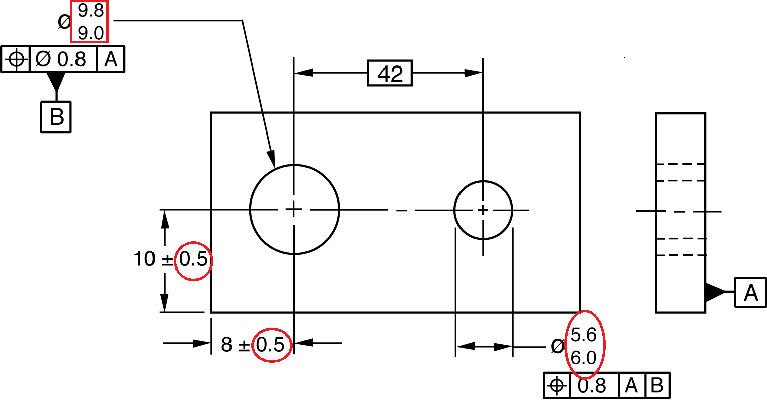
Limit Dimension We Can Specify Tolerances On The Drawing In The Way That Instead Of The Nominal Size And The Limit Deviation, We Enter The Upper Limit Of Size (Uls) And The Lower Limit Of Size (Lls).
Types and difference between unilateral & bilateral tolerance. Dimension tolerance dimension tolerance is the amount of variation allowed in a size. Web gd&t flatness is a common symbol that references how flat a surface is regardless of any other datum’s or features. Web the y14.5 standard is considered the authoritative guideline for the design language of geometric dimensioning and tolerancing (gd&t.) it establishes symbols, rules, definitions, requirements, defaults, and recommended practices for stating and interpreting gd&t and related requirements for use on engineering drawings, models defined in.
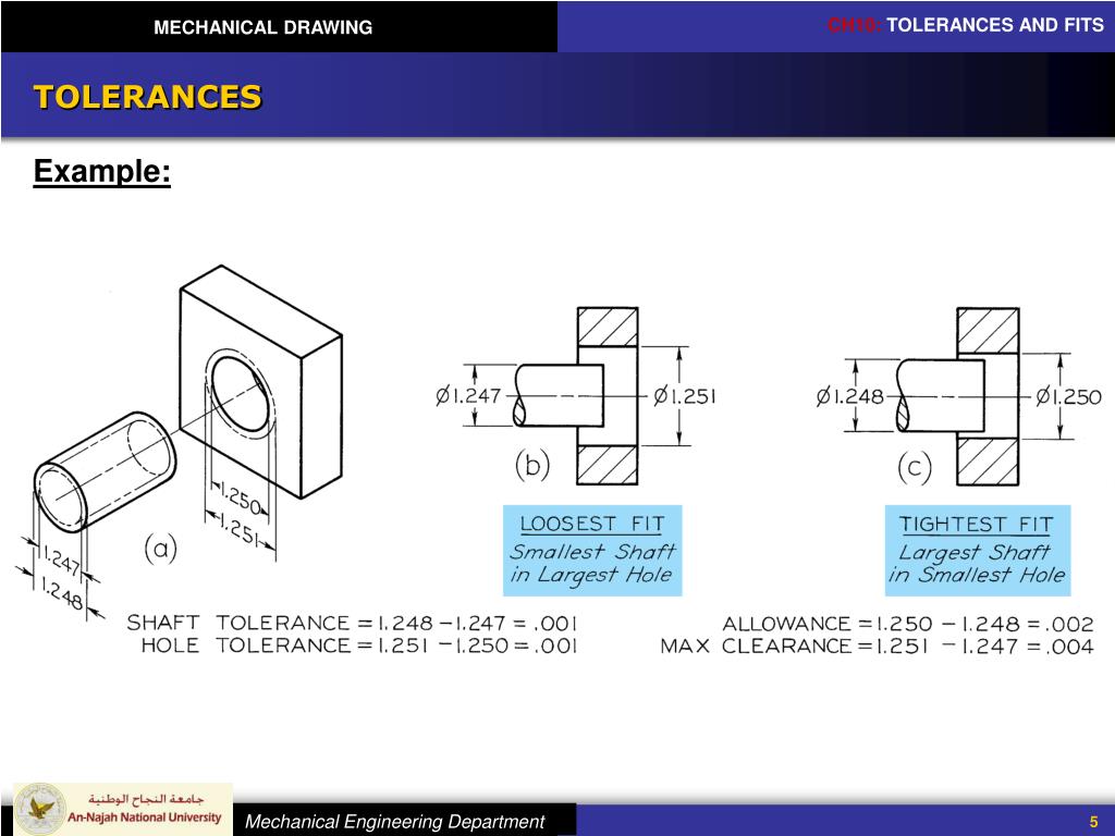
Web For Example, A Hole Is Located From An Edge By A Certain Amount (A Linear Dimension), Plus Or Minus A Smaller Amount (The Tolerance).
Graphics, dimensions, and words (notes). Limitations of tolerancing before gd&t Because it is impossible to make everything to an exact size, tolerances are used on production drawings to control the parts. Web when defining the tolerances on the engineering drawing, we can enter them in a few different ways: