
Legend In Engineering Drawing
Legend In Engineering Drawing - Each set of design drawings contains special notations that are unique for that project,. Piping and instrumentation diagrams commonly referred to as p&id’s are encountred nowadays throughout all process industries such as oil & gas, chemical, pharmaceutical or food industries. It comes in useful if a feature is to be defined on a drawing that needs to be uniformly flat without tightening any other dimensions on the drawing. Web gd&t flatness is a common symbol that references how flat a surface is regardless of any other datum’s or features. The key is in the bottom left or bottom right corner of the blueprint and contains the part name, part number,.
Eo 1.1 state the five types of information provided in the title block of an engineering drawing. We describe the algorithms and the experiments performed using this method. Piping and instrument diagram standard symbols detailed documentation provides a standard set of shapes & symbols for documenting p&id and pfd, including standard shapes of instrument, valves, pump, heating exchanges, mixers, crushers, vessels, compressors, filters,. Web an engineering drawing is a type of technical drawing that is used to convey information about an object. The engineering drawings, at first glance, look incomprehensible, they need to be comprehended by means of specific types of symbols and codes. Web look at the key (legend) first: Engineering drawing is a fundamental skill in many branches of engineering, including mechanical, electrical, and civil engineering.
Electrical Legend And Symbols Files, Plans and Details
So please watch the video till the end. This information is displayed in the areas surrounding the graphic portion of the drawing. Web the major goal is to take large sets of engineering drawing images and populate a database with the information from the legends of the drawings as automatically as possible. Web a legend.
Engineering Drawing Symbols And Their Meanings Pdf At DA9
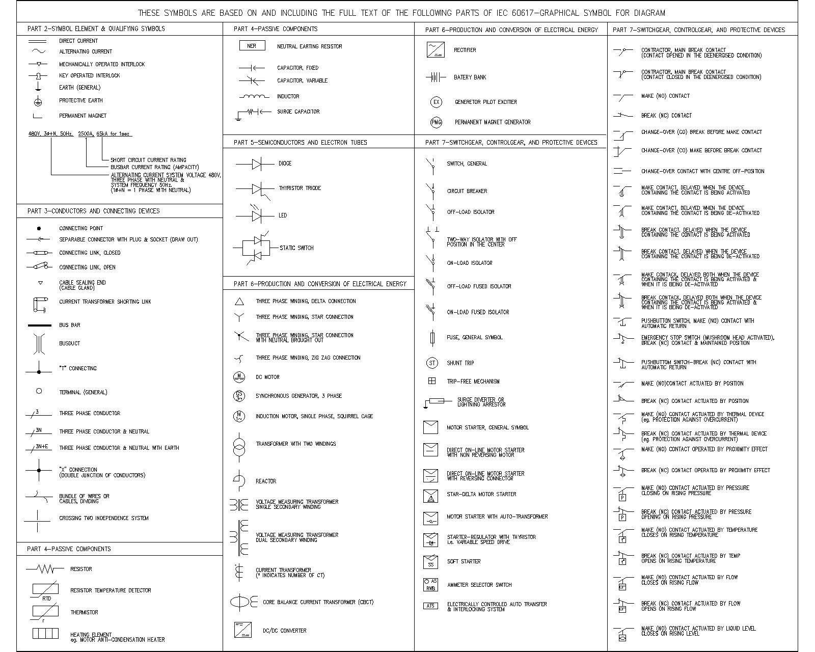
Web how to read engineering drawings? A common use is to specify the geometry necessary for the construction of a component and is called a detail drawing. Web basic electrical symbol legend shows a collection of graphic notations used to represent various electrical and electronic devices such as cell, battery, resister, heater, etc. Dimensioning and.
Engineering Drawing Symbols And Their Meanings Pdf at PaintingValley
If you want to learn how to read p&id and pfd, you must know the legend used in these drawings. Web notes and legends engineering drawing (graphic portion) the information contained in the drawing itself will be covered in subsequent modules. It comes in useful if a feature is to be defined on a drawing.

Engineering Drawing Symbols And Their Meanings Pdf at GetDrawings
This will help identify which type of cartoon is used in a particular position. The notes and legends section of a. Drawings are comprised of symbols and lines that represent components or systems. Web the major goal is to take large sets of engineering drawing images and populate a database with the information from the.

Engineering Drawing Symbols And Their Meanings Pdf at PaintingValley
Web an engineering drawing is a type of technical drawing that is used to convey information about an object. Web engineering drawing notes and legends. If you want to make yo. Piping and instrumentation diagrams commonly referred to as p&id’s are encountred nowadays throughout all process industries such as oil & gas, chemical, pharmaceutical or.

Engineering Drawing Symbols And Their Meanings Pdf at PaintingValley
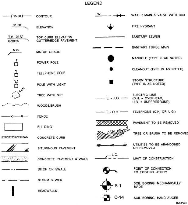
Web look at the key (legend) first: Eo 1.1 state the five types of information provided in the title block of an engineering drawing. If you want to make yo. A very detailed diagram showing the processes happening within a plant, the involved equipment, and their interconnections. Web identify the 5 key sections of your.

Engineering Drawing Symbols And Their Meanings Pdf at PaintingValley
Piping and instrumentation diagrams commonly referred to as p&id’s are encountred nowadays throughout all process industries such as oil & gas, chemical, pharmaceutical or food industries. A set of standardized p&id symbols is used by process engineers to draft such diagrams. Web look at the key (legend) first: So please watch the video till the.
Civil Engineering Drawing Symbols And Their Meanings at PaintingValley
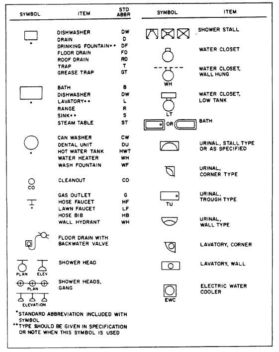
Web look at the key (legend) first: Similar to this concept, a legend in instrumentation drawing thus depicts which type of instrument is used in the drawing. Web the major goal is to take large sets of engineering drawing images and populate a database with the information from the legends of the drawings as automatically.

R.Land Baidin Egwar, ST MECHANICAL AND ELECTRICAL LEGEND AND SYMBOLS
Web engineering drawing notes and legends. A very detailed diagram showing the processes happening within a plant, the involved equipment, and their interconnections. Engineering drawing is a fundamental skill in many branches of engineering, including mechanical, electrical, and civil engineering. Drawings are comprised of symbols and lines that represent components or systems. The key is.

Construction Legend Construction Symbols, Construction Documents
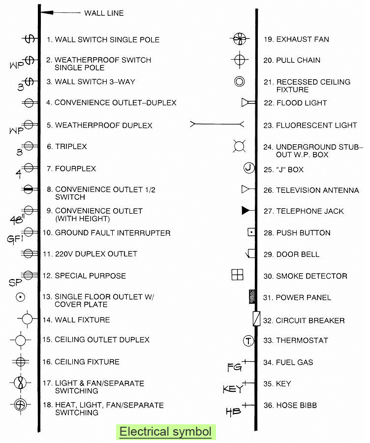
Article contents power symbols lighting symbols fire alarm symbols security symbols communications symbols power symbols duplex outlet weatherproof duplex outlet ground fault circuit interrupt duplex outlet The first four parts listed above provide important information about the actual drawing. The engineering drawings, at first glance, look incomprehensible, they need to be comprehended by means of.
Legend In Engineering Drawing Web an engineering drawing is a type of technical drawing that is used to convey information about an object. Web the major goal is to take large sets of engineering drawing images and populate a database with the information from the legends of the drawings as automatically as possible. Manual of engineering drafting and drawings. Web block, the notes and legend, and the drawing grid is necessary before a drawing can be read. So please watch the video till the end.
You Can Download This Presentation For Free.
Web p&id is the acronym for “piping and instrumentation diagram”, i.e. Engineering drawing is a fundamental skill in many branches of engineering, including mechanical, electrical, and civil engineering. Web notes and legends engineering drawing (graphic portion) the information contained in the drawing itself will be covered in subsequent modules. This information is displayed in the areas surrounding the graphic portion of the drawing.
Web Block, The Notes And Legend, And The Drawing Grid Is Necessary Before A Drawing Can Be Read.
The notes and legends section of a. Article contents power symbols lighting symbols fire alarm symbols security symbols communications symbols power symbols duplex outlet weatherproof duplex outlet ground fault circuit interrupt duplex outlet Piping and instrumentation diagrams commonly referred to as p&id’s are encountred nowadays throughout all process industries such as oil & gas, chemical, pharmaceutical or food industries. Each set of design drawings contains special notations that are unique for that project,.
The Key Is In The Bottom Left Or Bottom Right Corner Of The Blueprint And Contains The Part Name, Part Number,.
General arrangement (ga) drawings play a critical role in multiple industries, from architecture and civil engineering to industrial design. Pfd and p&id are also known as pfs and pefs. Piping and instrument diagram standard symbols detailed documentation provides a standard set of shapes & symbols for documenting p&id and pfd, including standard shapes of instrument, valves, pump, heating exchanges, mixers, crushers, vessels, compressors, filters,. Eo 1.2 state how the grid system on an engineering drawing is
Manual Of Engineering Drafting And Drawings.
So please watch the video till the end. Similar to this concept, a legend in instrumentation drawing thus depicts which type of instrument is used in the drawing. Dimensioning and tolerancing with 45 elements; They offer a comprehensive representation of an object or structure, demonstrating the location and connection of.