
Engineering Drawing Center Line
Engineering Drawing Center Line - Web center lines (figure \(\pageindex{5}\)) are used in drawings for several different applications. Web engineering lines can be classified into several categories based on their purpose and representation. Web center lines are widely used in the engineering drawings. It is used to show the center of a specific object. Web the standard line types used in technical drawings are center lines are used:
Two center lines crosses each other in the drawing. Please resubmit the plat on the correct size sheets. Depending on the layer chosen, the line will display it in a certain way. Web center lines are widely used in the engineering drawings. These lines are drawn beyond the object. A vicinity or site location map is needed. Common examples of such features include bolt holes, pins, discs, etc.

PPT Orthographic Projection PowerPoint Presentation ID466828
Web engineering lines can be classified into several categories based on their purpose and representation. This page provides a pdf copy of the traffic engineering signing and marking standard drawings. Hidden detail are shown with a certain line type to avoid confusion with visible edges. Most cad software packages will have these different line types.
Centerlines on Engineering Drawings and how they should be used
Let’s explore some of the most common types of lines used in engineering drawings: Web centerlines are one of the most frequently used tools in engineering drawing. A history of changes is available on the sms drawing change list. The issue date is provided to assist the user in determining the most. Depending on the.

Classifications of Civil Engineering Drawings and Interpreting
Please resubmit the plat on the correct size sheets. Web standard engineering drawing line types. Web there are 12 types of lines usually used in engineering drawing. At intersecting points, center lines should be drawn as short dashes. A vicinity or site location map is needed. The maximum allowable scale is 1”=100’. Their basic purpose.

SIEMENS NX DRAFTING 7 CENTERLINE (Circular, Bolt Circle, Symmetrical
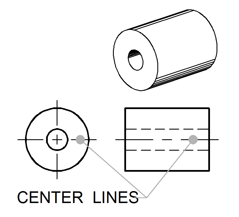
Common examples of such features include bolt holes, pins, discs, etc. Center lines in an engineering drawing show the center of a round or cylindrical shape. These lines are drawn beyond the object. A vicinity or site location map is needed. Web a student shared their viewpoint about the correct use of centerlines in engineering.
INCH Technical English engineering drawing
It is used to show the center of a specific object. Web centerlines are one of the most frequently used tools in engineering drawing. Web centerlines are annotations that mark the center between two line segments on a drawing view. Web signed drawings are on file in the traffic engineering office. Let’s explore some of.
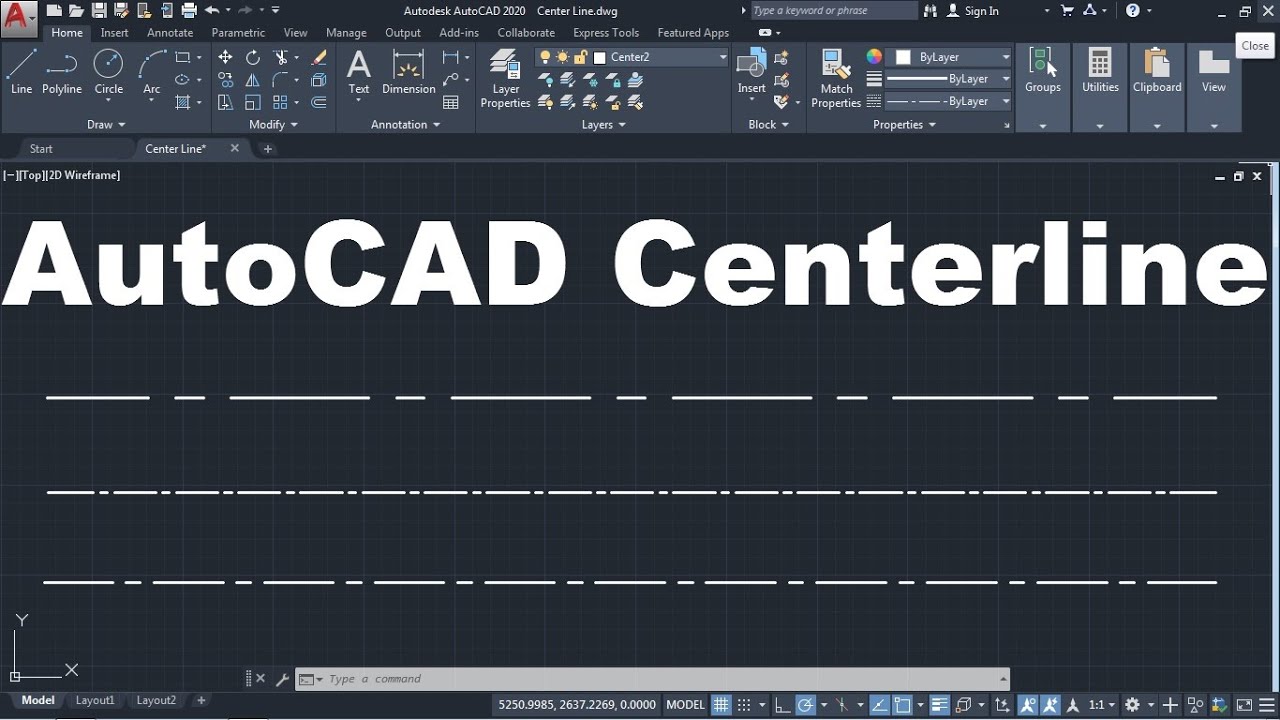
How to Draw Center line in AutoCAD YouTube
Web center lines are widely used in the engineering drawings. Web engineering lines can be classified into several categories based on their purpose and representation. Web graphics communications are used in every phase of engineering design starting from concept illustration all the way to the manufacturing phase. Web a student shared their viewpoint about the.

2020 Drawing Center Lines for an Orthographic Drawing YouTube
Web centre lines, lines of symmetry, trajectories, and pitch circles. Let’s explore some of the most common types of lines used in engineering drawings: A history of changes is available on the sms drawing change list. These lines are drawn as long, thin dashed lines and are used to indicate the center point of cylindrical.
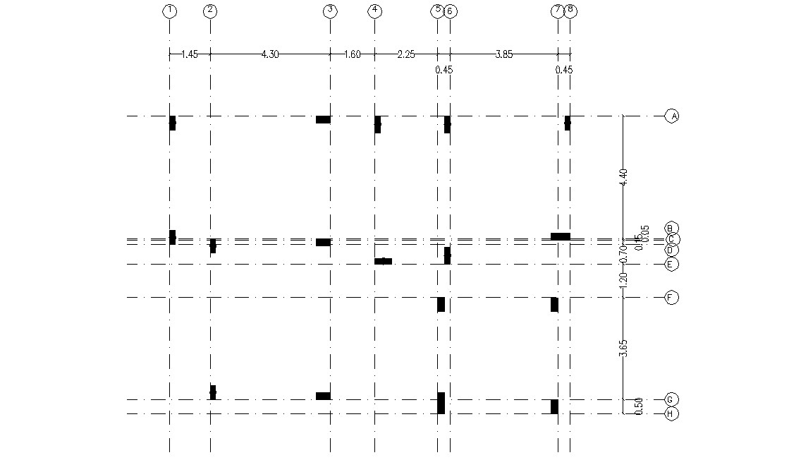
Simple Column Plan With Centre Line CAD Drawing Cadbull
At intersecting points, center lines should be drawn as short dashes. Common examples of such features include bolt holes, pins, discs, etc. The maximum allowable scale is 1”=100’. Web centerlines are one of the most frequently used tools in engineering drawing. Please resubmit the plat on the correct size sheets. Most cad software packages will.

how to draw center line plan of building by autocad for rcc design
Web center lines are an important element of engineering drawings that are used to represent the axis of symmetry for a part or assembly. Centre lines, lines of symmetry, trajectories, and pitch circles type of lines are long, thin, chain lines with alternately long and short dashes of proportion ranging from. This page provides a.
Center Lines ToolNotes
3d cad design and drafting services have come a very long way since the late 1990’s and early 2000’s.3d design software Center lines are also used to indicate the center of a circle or an arc. Long thin dashed and double short dashed lines this line is located in front of cutting planes, outlines of.
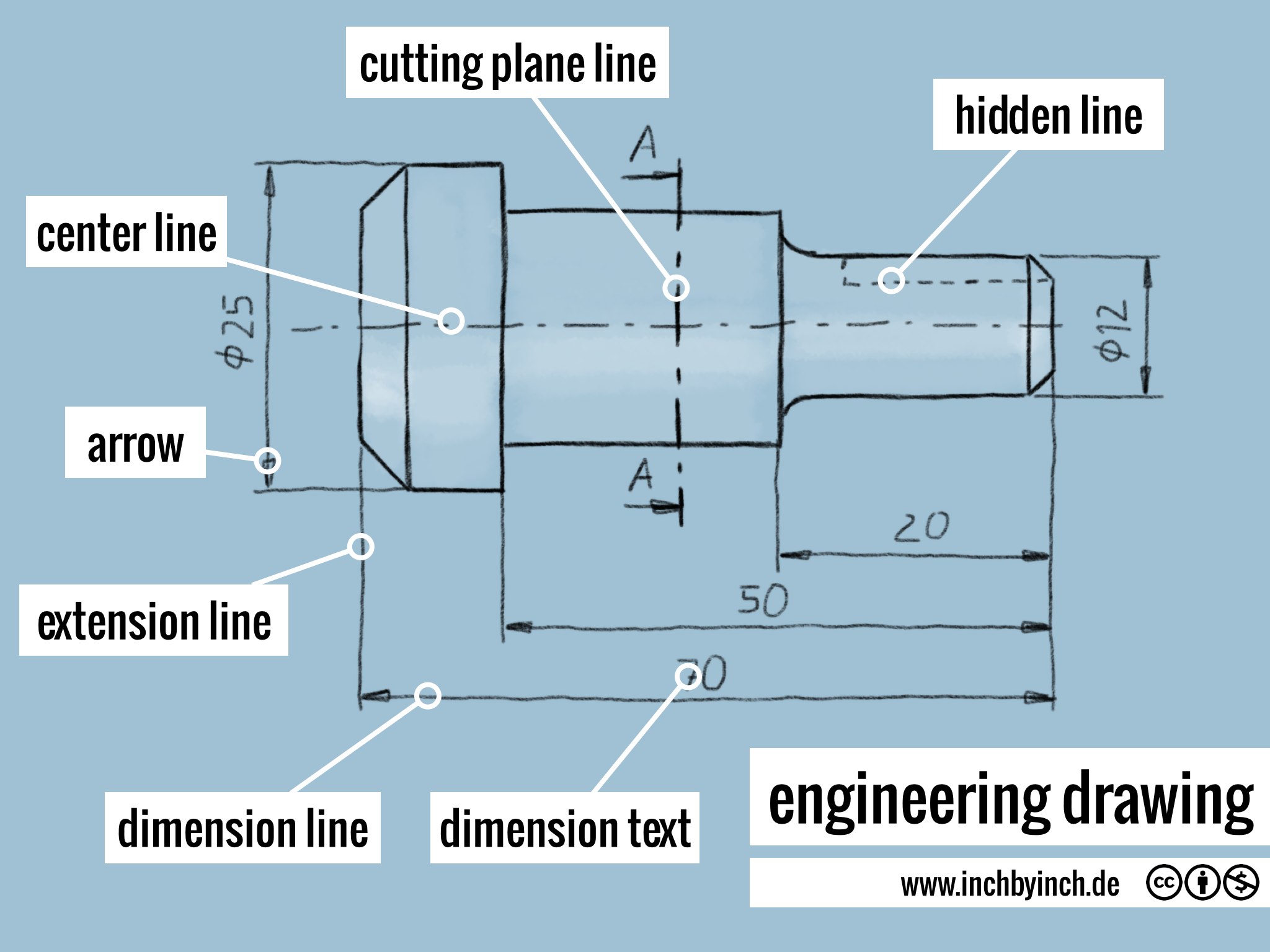
Engineering Drawing Center Line Web standard engineering drawing line types. Please resubmit the plat on the correct size sheets. Long thin dashed and double short dashed lines this line is located in front of cutting planes, outlines of adjacent parts, censorial lines, and to state center of gravity. A vicinity or site location map is needed. Visible lines hidden lines section lines center lines dimension lines extension lines leader lines cutting plane lines break lines phantom lines borderlines arrowheads visible lines they are dark and thick lines of any engineering design drawing.
Web Standard Engineering Drawing Line Types.
Long thin dashed and double short dashed lines this line is located in front of cutting planes, outlines of adjacent parts, censorial lines, and to state center of gravity. Please resubmit the plat on the correct size sheets. Web signed drawings are on file in the traffic engineering office. Web the third type of line used in engineering drawing is the center line.
A Variety Of Line Styles Graphically Represent Physical Objects.
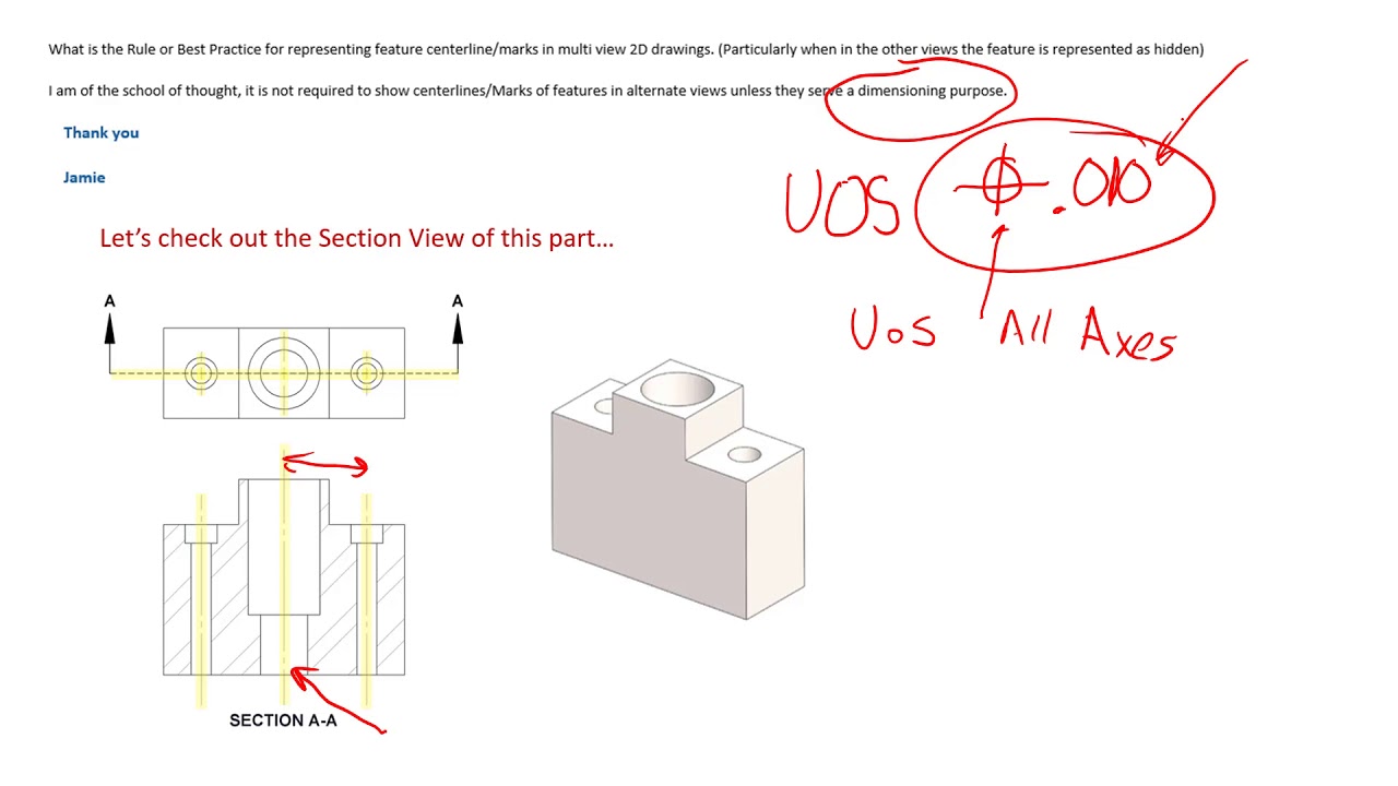
A history of changes is available on the sms drawing change list. Show the subdivision’s name on the preliminary plat. Web a student shared their viewpoint about the correct use of centerlines in engineering drawings, which was a bit conservative as they were missing a key application of th. Web centre lines, lines of symmetry, trajectories, and pitch circles.
The Maximum Allowable Scale Is 1”=100’.
A vicinity or site location map is needed. At intersecting points, center lines should be drawn as short dashes. We would like to shed light on an interesting discussion stemming from a question asked in our print reading and tolerances course. Web center lines are widely used in the engineering drawings.
The Scale Must Also Be Noted On Each Sheet.
Visible lines are the most fundamental type of lines used in engineering drawings. Web engineering lines can be classified into several categories based on their purpose and representation. Center lines in an engineering drawing show the center of a round or cylindrical shape. Web graphics communications are used in every phase of engineering design starting from concept illustration all the way to the manufacturing phase.