
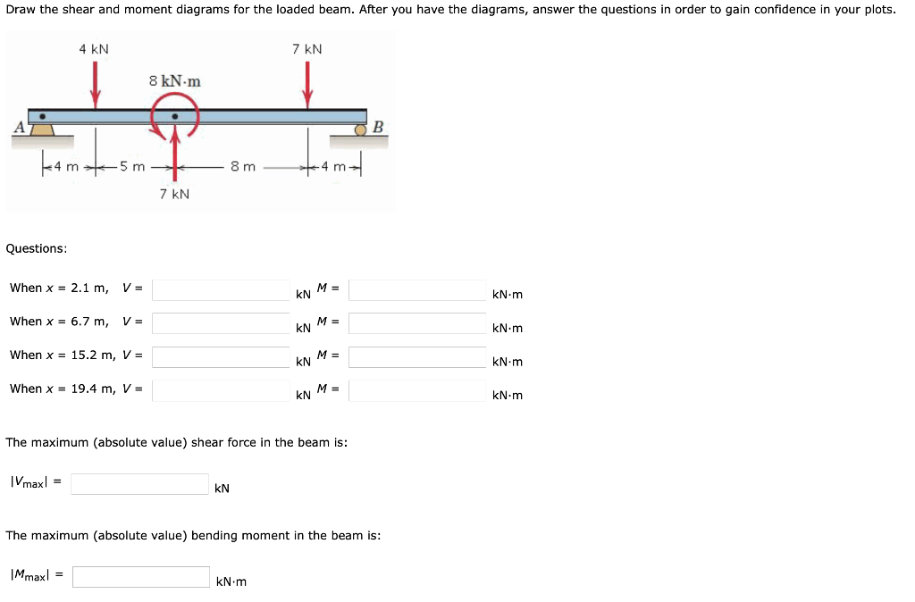
Draw The Shear And Moment Diagrams For The Loaded Beam
Draw The Shear And Moment Diagrams For The Loaded Beam - (a) draw complete shear and moment diagrams (b) design the cross section of the beam, knowing that the grade of timber used has an allowable normal stress of 1,200psi and an allowable shear stress of 120psi. This problem has been solved! Also, draw shear and moment diagrams, specifying values at all change of loading positions and at points of zero shear. Mechanical engineering questions and answers. For the beam and loading shown:
Web subscribe and like this video for more such problems. The bending moment at a section of a beam can be determined by summing up the moment. By drawing the free body diagram you identify all of these loads and show then on a sketch. Also, draw shear and moment diagrams, specifying values at all change of loading positions and at points of zero shear. Beam shear 21131 fixed at both ends—uniformly loads total equiv. Also draw shear force diagram (sfd) and bending moment diagram (bmd). Please show all your working.

Solved Draw the shear and moment diagrams for the beam.
Skyciv beam tool guides users along a professional beam calculation workflow, culminating in the ability to view and determine if they comply with your region's design codes. Please show all your working. Web the first step in calculating these quantities and their spatial variation consists of constructing shear and bending moment diagrams, \(v(x)\) and \(m(x)\),.
Solved Draw the shear and moment diagrams for the loaded
You’ll have your own analysis software that can generate shear force diagrams, bending moment diagrams, deflected shapes and more. Draw the shear and moment diagrams for the loaded cantilever beam. You'll get a detailed solution from a subject matter expert. Also draw shear force diagram (sfd) and bending moment diagram (bmd). Web introduction figures 1.

Shear force and bending moment diagrams for a simply supported beam
By drawing the free body diagram you identify all of these loads and show then on a sketch. What are the values of the shear force and bending moment at the middle of the beam? Give numerical values at all change of loading positions and at all points of zero shear. Shear and moment diagrams.

Bending moment and shear force diagram of a cantilever beam
Web our calculator generates the reactions, shear force diagrams (sfd), bending moment diagrams (bmd), deflection, and stress of a cantilever beam or simply supported beam. Label all significant points on each diagram. Free body diagram of the given figure is given below; 1 example 8 the beam is loaded and supported as shown in the.

Learn How To Draw Shear Force And Bending Moment Diagrams Engineering
Determine the maximum value of (a) the internal shear force and (b) the internal bending. The bending moment at a section of a beam can be determined by summing up the moment. Web subscribe and like this video for more such problems. Web draw the shear and moment diagrams for the linearly loaded cantilever beam.
Solved Draw the shear and moment diagrams for the loaded
Let a = 5.0 ft, b = 4.5 ft, p = 21 kips, and w = 3.0 kips/ft. The bending moment at a section of a beam can be determined by summing up the moment. Web since the function for the bending moment is parabolic, the bending moment diagram is a curve. Draw the shear.

Shear force and bending moment diagrams for beams pdf
In addition to the two principal values of bending moment at x = 0 m and at x = 5 m, the moments at other intermediate points should be determined to correctly draw the bending moment diagram. We go through breaking a beam into segments, and then we learn about the relationships between shear force.

Drawing Shear and Moment Diagrams for Beam YouTube
In each problem, let x be the distance measured from left end of the beam. Web civil engineering civil engineering questions and answers draw the shear and moment diagrams for the loaded beam. Free body diagram of the given figure is given below; Draw the shear and moment diagrams for the loaded cantilever beam. This.
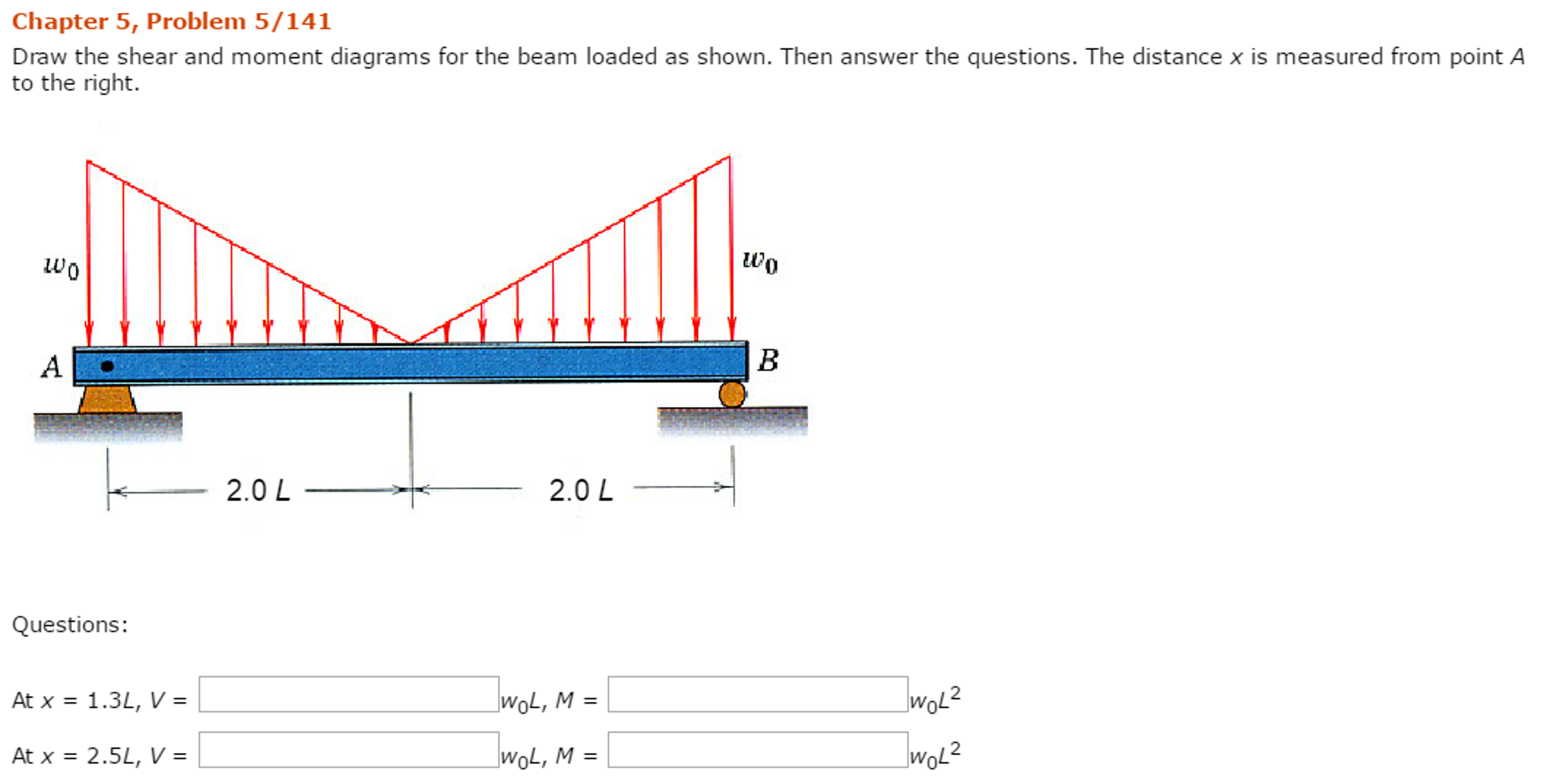
Solved Draw the shear and moment diagrams for the beam
Web this is an example problem that will show you how to graphically draw a shear and moment diagram for a beam. Let a = 5.0 ft, b = 4.5 ft, p = 21 kips, and w = 3.0 kips/ft. Please show all your working. Also, draw shear and moment diagrams, specifying values at all.

Brief Information About Shear Force And Bending Moment Diagrams
What are the values of the shear force and bending moment at the middle of the beam? Web this is an example problem that will show you how to graphically draw a shear and moment diagram for a beam. Shear and moment diagrams and formulas are excerpted from the western woods use book, 4th edition,.
Draw The Shear And Moment Diagrams For The Loaded Beam Let a = 5.0 ft, b = 4.5 ft, p = 21 kips, and w = 3.0 kips/ft. What are the values of the shear force and bending moment at the middle of the beam? Determine the maximum value of (a) the internal shear force and (b) the internal bending. Please show all your working. Also draw shear force diagram (sfd) and bending moment diagram (bmd).
Web Our Calculator Generates The Reactions, Shear Force Diagrams (Sfd), Bending Moment Diagrams (Bmd), Deflection, And Stress Of A Cantilever Beam Or Simply Supported Beam.
Web let the shear force and bending moment at a section located at a distance of x from the left support be v and m, respectively, and at a section x + dx be v + dv and m + dm, respectively. You’ll have your own analysis software that can generate shear force diagrams, bending moment diagrams, deflected shapes and more. We go through breaking a beam into segments, and then we learn about the relationships between shear force and moment. Determine the values of the shear force and bending moment at midbeam.
Web Since The Function For The Bending Moment Is Parabolic, The Bending Moment Diagram Is A Curve.
Web the first step in calculating these quantities and their spatial variation consists of constructing shear and bending moment diagrams, \(v(x)\) and \(m(x)\), which are the internal shearing forces and bending moments induced in. Write shear and moment equations for the beams in the following problems. (a) draw complete shear and moment diagrams (b) design the cross section of the beam, knowing that the grade of timber used has an allowable normal stress of 1,200psi and an allowable shear stress of 120psi. Web 2) calculate the shear force and bending moment diagram of the beam as shown in the figure.
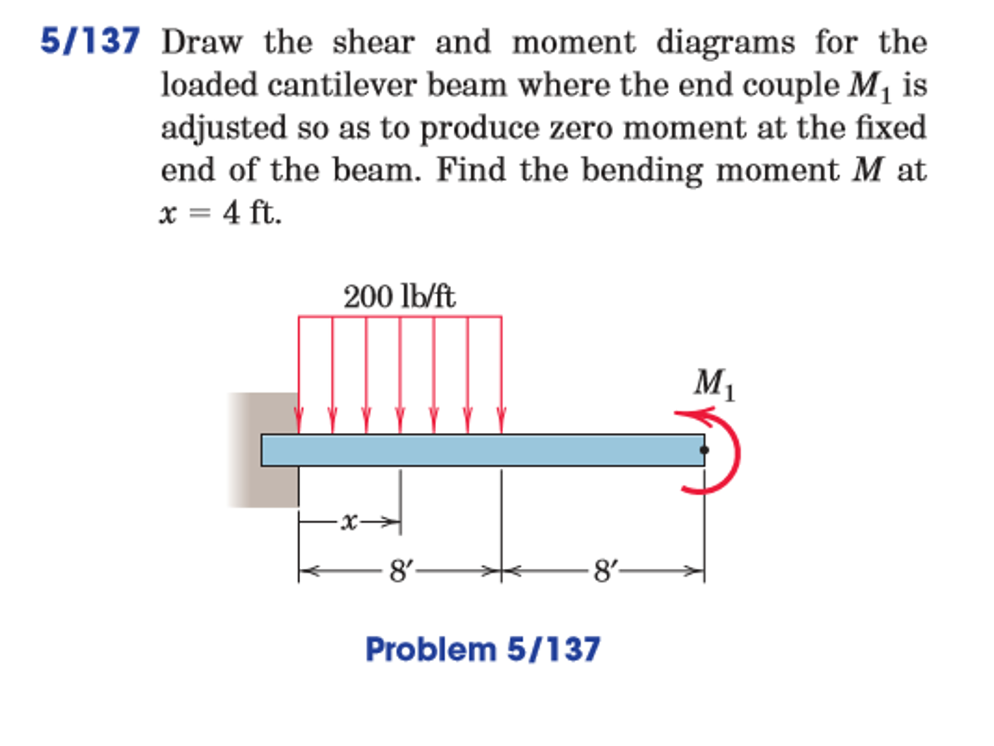
Draw The Shear And Moment Diagrams For The Loaded Cantilever Beam.
The total load acting through the center of the infinitesimal length is wdx. Also, draw shear and moment diagrams, specifying values at all change of loading positions and at points of zero shear. Please show all your working. State the value of the bending moment at midbeam.
Web Subscribe And Like This Video For More Such Problems.
Web introduction figures 1 through 32 provide a series of shear and moment diagrams with accompanying formulas for design of beams under various static loading conditions. Web this video explains how to draw shear force diagram and bending moment diagram with easy steps for a simply supported beam loaded with a concentrated load. Web civil engineering civil engineering questions and answers draw the shear and moment diagrams for the loaded beam. [collapse collapsed title=click here to read or hide the general instruction]without writing shear and moment equations, draw the shear and moment diagrams for the beams specified in the following problems.