
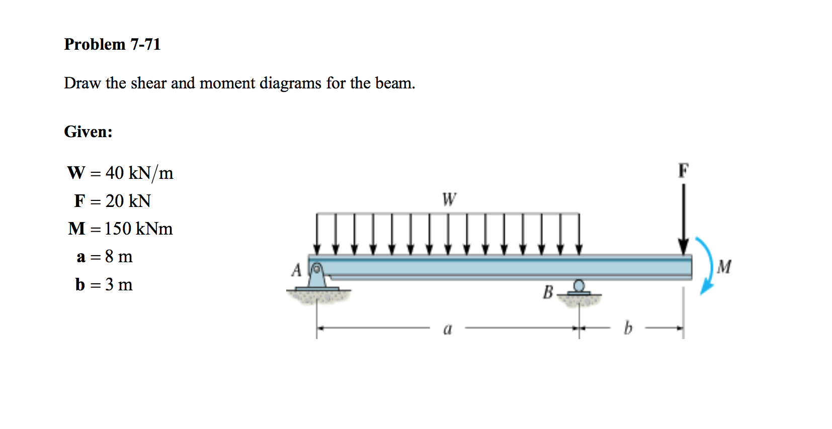
Draw Shear And Moment Diagrams For The Beam
Draw Shear And Moment Diagrams For The Beam - Web this video explains how to draw shear force diagram and bending moment diagram with easy steps for a simply supported beam loaded with a concentrated load. For the beam of figure 4: Assume the upward reaction provided by the ground to be uniformly distributed. Web draw the shear and moment diagrams for the beam and determine the shear and moment in the beam as functions of x, where 4 ft < x < 10 ft. Web 100% (1 rating) step 1 reaction at support = ay ay = 8 × 1.5 + 6 = 18 view the full answer step 2 unlock answer unlock previous question next question transcribed image text:
Determine the maximum value of (a) the internal shear force and (b) the internal bending. B will be to write the and mcnnent quations. If you’re not in the mood. R − 6 × 9 1 (9) 9 × 0 2 3 ∴ r = 9 kn a This page will walk you through what shear forces and bending moments are, why they are useful, the procedure for drawing the diagrams and some other keys aspects as well. Web a bending moment diagram is one which shows variation in bending moment along the length of the beam. Web write shear and moment equations for the beams in the following problems.

Drawing Shear and Moment Diagrams for Beam YouTube
We go through breaking a beam into segments, and then we learn about the relationships between shear force. Taking moment about point b , we get. Web this video explains how to draw shear force diagram and bending moment diagram with easy steps for a simply supported beam loaded with a concentrated load. Label all.

Solved Draw the shear and moment diagrams for the beam
Web shear force and bending moment diagrams are powerful graphical methods that are used to analyze a beam under loading. Draw a free body diagram of the beam with global coordinates (x) calculate the reaction forces using equilibrium equations ( ∑ forces = 0 and ∑ moments = 0 ). W = load per unit.

Learn How To Draw Shear Force And Bending Moment Diagrams Engineering
P = total concentrated load, lbs. We go through breaking a beam into segments, and then we learn about the relationships between shear force. Web the shear force and the bending moment usually vary continuously along the length of the beam. Web since the function for the bending moment is parabolic, the bending moment diagram.

Learn How To Draw Shear Force And Bending Moment Diagrams Engineering
Web this problem has been solved! Web draw the shear and moment diagrams for the beam and determine the shear and moment in the beam as functions of x, where 4 ft < x < 10 ft. Assume the upward reaction provided by the ground to be uniformly distributed. Web 2) calculate the shear force.
Solved Draw the shear and moment diagrams for the beam.
Also, draw shear and moment diagrams, specifying values at all change of loading positions and at. Example 1 draw the shear force and bending moment diagrams for the beam shown below a) determine the reactions at the supports. Also draw shear force diagram (sfd) and bending moment diagram (bmd). Web 2) calculate the shear force.
Solved Draw the Shear and Moment Diagram for the beam shown
Determine the maximum value of (a) the internal shear force and (b) the internal bending. Web in solid mechanics, a bending moment is the reaction induced in a structural element when an external force or moment is applied to the element, causing the element to bend. Label all significant points on each diagram. Skyciv beam.

Shear force and bending moment diagrams for a simply supported beam
W = total uniform load, lbs. Assume the upward reaction provided by the ground to be uniformly distributed. Web 2) calculate the shear force and bending moment diagram of the beam as shown in the figure. Label all significant points on each diagram. The shear and bending moment at x are then. In addition to.

Solved Draw the shear and moment diagrams for the beam.
Also, draw shear and moment diagrams, specifying values at all change of loading positions and at. Assume the upward reaction provided by the ground to be uniformly distributed. No elements selected draw the shear and moment diagrams for the. Free body diagram of the given figure is given below; Web write shear and moment equations.

Solved Draw the shear and moment diagrams for the beam, and
This page will walk you through what shear forces and bending moments are, why they are useful, the procedure for drawing the diagrams and some other keys aspects as well. Web steps to construct shear force and bending moment diagrams. 200 lb ft b x 4 ft 4 ft 150 lb/ft 6 ft 200 lb.

Solved Draw the shear and moment diagrams for the beam (a)
Web this video explains how to draw shear force diagram and bending moment diagram with easy steps for a simply supported beam loaded with a concentrated load. The reactions shown on the diagram are determined from equilibrium equations as follows: Web steps to construct shear force and bending moment diagrams. Assume the upward reaction provided.
Draw Shear And Moment Diagrams For The Beam Mechanical engineering questions and answers. B will be to write the and mcnnent quations. V = shear force, lbs. The reactions shown on the diagram are determined from equilibrium equations as follows: Web shear force and bending moment diagrams are powerful graphical methods that are used to analyze a beam under loading.
Web A Bending Moment Diagram Is One Which Shows Variation In Bending Moment Along The Length Of The Beam.
Web our calculator generates the reactions, shear force diagrams (sfd), bending moment diagrams (bmd), deflection, and stress of a cantilever beam or simply supported beam. Web write equations for the shear v and bending moment m for any section of the beam in the interval ab. [1] [2] the most common or simplest structural element subjected to bending moments is the beam. The bending moment diagram of the.
Internal Forces 6.2 Shear/Moment Diagrams 6.2.1 What Are Shear/Moment Diagrams?
For the beam and loading shown: Free body diagram of the given figure is given below; Let a = 5.0 ft, b = 4.5 ft, p = 21 kips, and w = 3.0 kips/ft. Web steps to construct shear force and bending moment diagrams.
No Elements Selected Draw The Shear And Moment Diagrams For The.
(1) normal stress that is caused by bending moment and. Draw the shear and moment diagrams for the cantilevered beam. Draw the shear and moment diagrams for the beam. You’ll have your own analysis software that can generate shear force diagrams, bending moment diagrams, deflected shapes and more.
Draw The Shear And Moment Diagrams For The Beam In (Figure 1).
Web shear force and bending moment diagrams are powerful graphical methods that are used to analyze a beam under loading. Also draw shear force diagram (sfd) and bending moment diagram (bmd). R − 6 × 9 1 (9) 9 × 0 2 3 ∴ r = 9 kn a Also, draw shear and moment diagrams, specifying values at all change of loading positions and at.