Draw A Gear
Draw A Gear - Φ = pressure angle a = addendum a g = addendum of gear a p = addendum of pinion b = dedendum c = clearance c = center distance d = pitch diameter d g = pitch diameter of gear d p = pitch diameter of pinion d b = base circle diameter d o = outside diameter dr = root diameter f = face width Gears can be animated with various speed to demonstrate working mechanism. Add small triangles to each section to represent. In this case, you will need to set the compass radius to ½ of 3,5 cm (35 mm), which is 17,5 mm. When it comes to drawing a gear, getting the proportions right is essential.
Popular file formats for gear designs are step, stl, iges, dxf. Divide the circle into equal parts divide the circle into equal parts using a ruler. Depending upon the type and accuracy of motion desired, the gears and the profiles of the gear teeth can be of almost any form. Draw the pitch circle using a compass. Web designing gears in solidworks involves a few steps: Use the “smart dimension” tool to set the diameter of the circle. Draw another circle inside the first one for the root diameter.
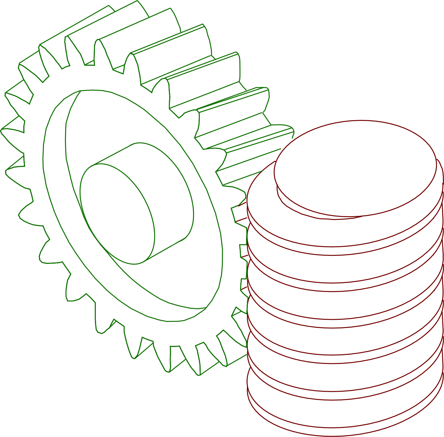
Mechanical Gears Drawing at Explore collection of
How to draw a gear step by step for kids. We are now just over two months away from kde's megarelease. In this case, you will need to set the compass radius to ½ of 3,5 cm (35 mm), which is 17,5 mm. In addition it let you compose full gear layouts with connetcted gears.
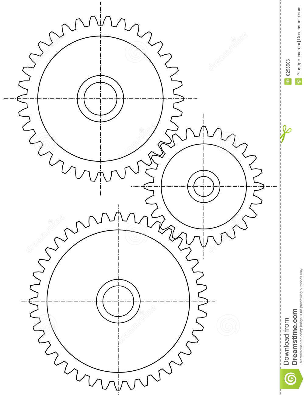
technical drawing gear Technical drawing, Gear drawing, Mechanical
Cars, clocks, and can openers, along with many other devices, use gears in their mechanisms to transmit power through rotation. Next step is to determine the pitch and roller diameter for your chain size. Start a new part and create a sketch on the front plane. Web how to draw a gear: Web learn gear.
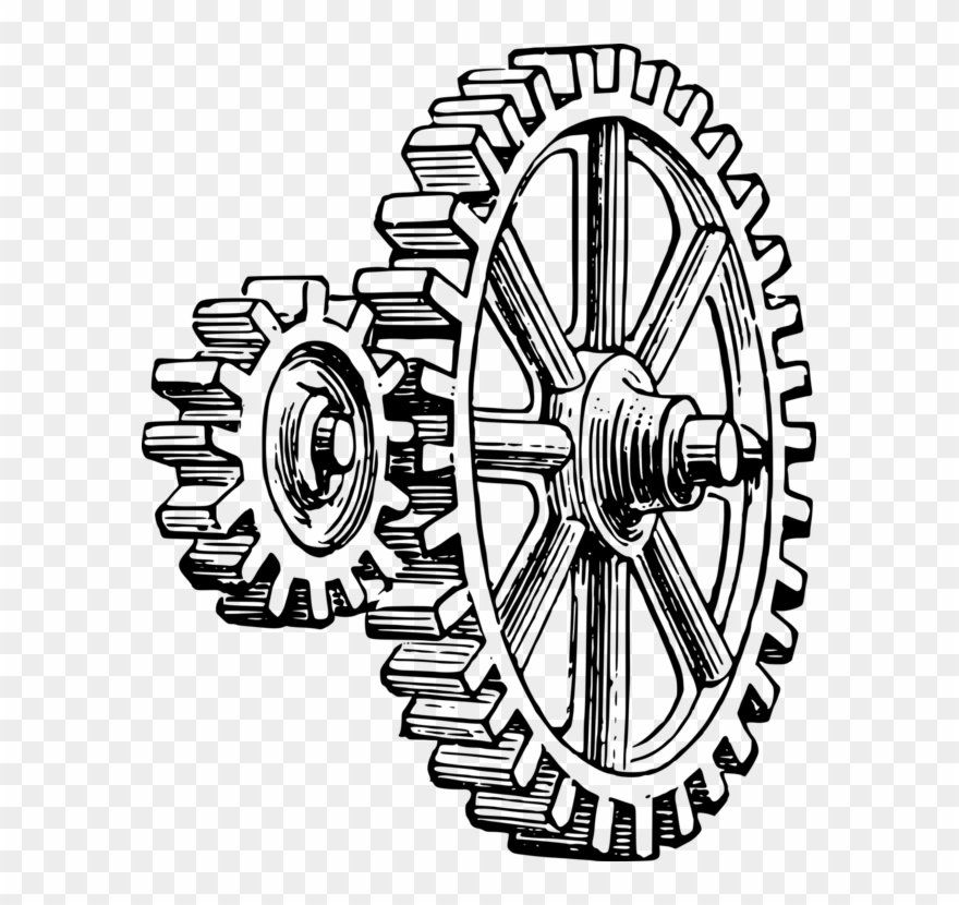
Simple Gear Drawing at GetDrawings Free download
Web designing gears in solidworks involves a few steps: Output your file directly to your cad program for 3d printing, routing, laser cutting, water jet cutting. Make sure inches is selected in the toolbar and the lock button looks locked. Draw the pitch circle using a compass. Divide the circle into equal sections using horizontal.
Simple Gear Drawing at Explore collection of
Web how to draw a gear? Draw the base circle of one gear (since the gear ratio is 1:1, we only need to draw one). Depending upon the type and accuracy of motion desired, the gears and the profiles of the gear teeth can be of almost any form. Web designing gears in solidworks involves.
How To Draw a Gear Step By Step For Kids YouTube
In this case, you will need to set the compass radius to ½ of 3,5 cm (35 mm), which is 17,5 mm. Output your file directly to your cad program for 3d printing, routing, laser cutting, water jet cutting. Depending upon the type and accuracy of motion desired, the gears and the profiles of the.
Draw a gear in Adobe Illustrator YouTube
Zoom in if you need to. Now that you have a basic idea of what a gear is and how it works, let's see how to draw one easily and simply. Web how to draw a gear? Draw another circle inside the first one for the root diameter. To draw that circle i need to.
Mechanical Gears Drawing at GetDrawings Free download
In this tutorial, i will walk you through the process of drawing a gear, providing clear and concise instructions to help you create an accurate and realistic gear design. Web use the circle tool and hold down the ctrl button (on a pc) to draw a circle inside the big gear. It is important to.
GEAR DRAWING how to draw gears by hand YouTube
Next step is to determine the pitch and roller diameter for your chain size. Web a list of steps for making the gear is also shown below (and every value can be found in the spreadsheet); How to draw a gear step by step for kids. Web learn gear drawing and know how to draw.
Simple Gear Drawing at GetDrawings Free download
Zoom in if you need to. Every few years we port the key components of our software to a new version of qt, taking the opportunity to remove cruft and leverage the updated features the most recent version of qt has to offer us. Draw another circle inside the first one for the root diameter..
Handdrawn gear illustration free image by / Noon How
Web learn gear drawing and know how to draw gears by hand. Make sure the arrow selector is active and click on the circle. Draw a circle using a compass, draw a circle on your paper. Depending upon the type and accuracy of motion desired, the gears and the profiles of the gear teeth can.
Draw A Gear Start by drawing a circle to represent the shape of the gear. Gears are a type of circular mechanical device with teeth that mesh to. Depending upon the type and accuracy of motion desired, the gears and the profiles of the gear teeth can be of almost any form. Φ = pressure angle a = addendum a g = addendum of gear a p = addendum of pinion b = dedendum c = clearance c = center distance d = pitch diameter d g = pitch diameter of gear d p = pitch diameter of pinion d b = base circle diameter d o = outside diameter dr = root diameter f = face width Web lets start with a gear tooth size of 10 mm.
In This Case, You Will Need To Set The Compass Radius To ½ Of 3,5 Cm (35 Mm), Which Is 17,5 Mm.
Web lets start with a gear tooth size of 10 mm. Popular file formats for gear designs are step, stl, iges, dxf. Output your file directly to your cad program for 3d printing, routing, laser cutting, water jet cutting. Exit the sketch and create a new sketch on the same plane.
The First Thing You Will Need Is A Drafting Program To Draw The Sprocket Gear.
In addition it let you compose full gear layouts with connetcted gears to design multiple gears system with control of the input/output ratio and rotation speed. Draw the profiles of the gear teeth using lines radiating from the center of the circles. Next step is to determine the pitch and roller diameter for your chain size. Depending upon the type and accuracy of motion desired, the gears and the profiles of the gear teeth can be of almost any form.
Start By Drawing A Circle To Represent The Shape Of The Gear.
Now that you have a basic idea of what a gear is and how it works, let's see how to draw one easily and simply. Gears can be animated with various speed to demonstrate working mechanism. In this tutorial, i will walk you through the process of drawing a gear, providing clear and concise instructions to help you create an accurate and realistic gear design. Draw the base circle of one gear (since the gear ratio is 1:1, we only need to draw one).
Every Few Years We Port The Key Components Of Our Software To A New Version Of Qt, Taking The Opportunity To Remove Cruft And Leverage The Updated Features The Most Recent Version Of Qt Has To Offer Us.
Web don't miss my: Web designing gears in solidworks involves a few steps: Draw two crossing centrelines to mark the centre of the gear wheel. Web spur gear design calculator where:

