Dimensioning In Engineering Drawing
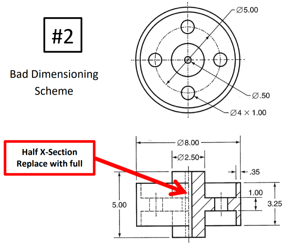
Dimensioning In Engineering Drawing - Dimensions must be placed in appropriate positions. Web the purpose of engineering drawings. These are indicated on the engineering drawing to define the size characteristics such as length, height, breadth, diameter, radius, angle, etc. Geometrics is the science of specifying and tolerancing the shapes and locations of features on objects. Web dimensioning on the engineering drawing is probably the most challenging part of the drawing creation.
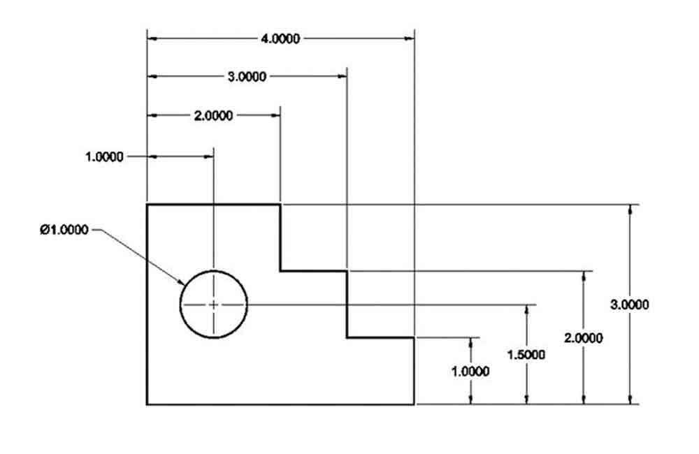
To avoid having many dimensions extending away from the part, arrowless dimensioning may be used. The engineering drawings prepared by. Chain dimensioning is a dimensioning system that dimensions from point to point. Web dimensioning is the process of defining the size, form and location of geometric features and components on an engineering drawing. Mark the fixed size of the shape one by one. The next step to upgrade your dimensioning skills is. Web the purpose of engineering drawings.
Types Of Dimensions In Engineering Drawing at GetDrawings Free download
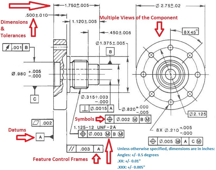
The assembly can be divided into five basic parts: Engineering drawing has evolved into a language that uses an extensive set of conventions to convey information very precisely, with very little ambiguity. The standard unit of length in si units is the meter. Web “the y14.5 standard is considered the authoritative guideline for the design.
Types Of Dimensions In Engineering Drawing at GetDrawings Free download
In drawing practice, the preferred si unit of length is the millimeter. Before an object can be built, complete information about both the size and shape of the object must be available. Once the shape of a part is defined with an orthographic drawings, the size information is added also in the form of dimensions..
Dimensioning and sectioning in engineering drawing. Engineering Drawing
We are going to look at what dimensioning is, what are the elements of the dimensions and what the rules for. Correct values must be given. The standard unit of length in si units is the meter. Avoid dimensioning hidden lines wherever possible. Place dimensions on views that show parts of features as solid outlines..
Types Of Dimensions In Engineering Drawing at GetDrawings Free download
Web “the y14.5 standard is considered the authoritative guideline for the design language of geometric dimensioning and tolerancing (gd&t.) it establishes symbols, rules, definitions, requirements, defaults, and recommended practices for stating and interpreting gd&t and related requirements for use on engineering drawings, models defined in. Web steps to dimensioning: Select the dimension datum, select the.
Lecture Notes Engineering Drawing Part 4
Try to keep dimensions between views. A complete set of dimensions will permit only one interpretation needed to construct the part. Or it is a series of. It may seem a bit basic, but a few exercises with the shapes of numbers comes before dimensioning. As already said, such a technical drawing has all the.
1.4aPlacing of Dimension Systems in Engineering Drawing Aligned and
Dimensions are required for points, lines, and surfaces that are related functionally or control relationship of other features. The next step to upgrade your dimensioning skills is. The assembly can be divided into five basic parts: Fractions are not allowed in si units, only decimal values are allowed. Dimensioning a drawing also identifies the tolerance.
GENERAL RULES OF DIMENSIONING in Engineering Drawing YouTube
Fractions are not allowed in si units, only decimal values are allowed. Avoid dimensioning hidden lines wherever possible. The standard unit of length in si units is the meter. Leave adequate room between views when you begin your sketch. Web in this video, we are going to learn about dimensions in engineering drawing! As already.
Dimensioning and its role in drafting and design
Dimensioning should follow these guidelines. It describes typical applications and minimum content. To avoid having many dimensions extending away from the part, arrowless dimensioning may be used. The exact shape of the part or assembly is shown by the different views in the drawing sheet. Basic dimensioning is the addition of. Parallels, running, chains, &.
Dimensioning Its Types, System, Principles. [A Comprehensive Guide].
Basic dimensioning is the addition of. Engineering drawing has evolved into a language that uses an extensive set of conventions to convey information very precisely, with very little ambiguity. To avoid having many dimensions extending away from the part, arrowless dimensioning may be used. The dimension line is a fine, dark, solid line with arrowheads.
System of dimensioning, Dimensioning methods in Engineering Drawing
Geometrics is the science of specifying and tolerancing the shapes and locations of features on objects. Or it is a series of. A complete set of dimensions will permit only one interpretation needed to construct the part. Web dimensioning on the engineering drawing is probably the most challenging part of the drawing creation. Try to.
Dimensioning In Engineering Drawing Leave adequate room between views when you begin your sketch. Web “dimensioning” in engineering drawings are numerical values indicated graphically in a proper unit of measurement on engineering drawing with lines, symbols, and notes. Web dimensioning practice dimension elements. A complete set of dimensions will permit only one interpretation needed to construct the part. A complete set of dimensions will permit only one interpretation needed to construct the part.
Correct Values Must Be Given.
Web dimensions in engineering drawings are numerical values indicated graphically in a proper unit of measurement on engineering drawing with lines, symbols, and notes. Parallels, running, chains, & combined amplitude. Web dimensioning a drawing is about adding dimension, notes, & lines to a drawing. So once a manufacturing engineer gets the drawing, he can start the production process without a.
You Can See That There Are Many Basic Rules, And That Is Not Even The Hard Part.
It describes typical applications and minimum content. Web the purpose of dimensioning is to provide a clear and complete description of an object. Basic dimensioning is the addition of. Or it is a series of.
A Complete Set Of Dimensions Will Permit Only One Interpretation Needed To Construct The Part.
The dimension line is a fine, dark, solid line with arrowheads on each end. A complete set of dimensions will permit only one interpretation needed to construct the part. To avoid having many dimensions extending away from the part, arrowless dimensioning may be used. Some methods of dimensioning a drawing can produce an accumulated error.
The Exact Shape Of The Part Or Assembly Is Shown By The Different Views In The Drawing Sheet.
Dimensions must be placed in appropriate positions. In drawing practice, the preferred si unit of length is the millimeter. As already said, such a technical drawing has all the information for manufacturing a part or welding and building an assembly.the info includes dimensions, part names and numbers, etc. The standard unit of length in si units is the meter.


![Dimensioning Its Types, System, Principles. [A Comprehensive Guide].](https://civilseek.com/wp-content/uploads/2018/10/dimensioning.jpg)
