
Diameter Engineering Drawing
Diameter Engineering Drawing - Basic dimensioning is the addition of only functional size values to drawing entities. The reasons for using geometric dimensioning and tolerancing (gd&t) are: Web an engineering drawing is a subcategory of technical drawings. A complete understanding of the object should be possible from the drawing. It is a system of symbols and standards used by engineers to provide manufacturing information to the production team.
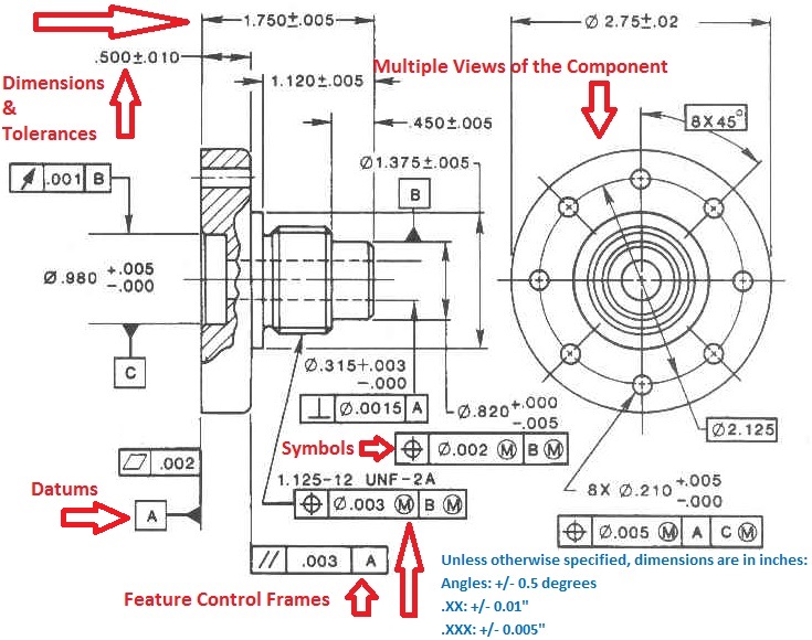
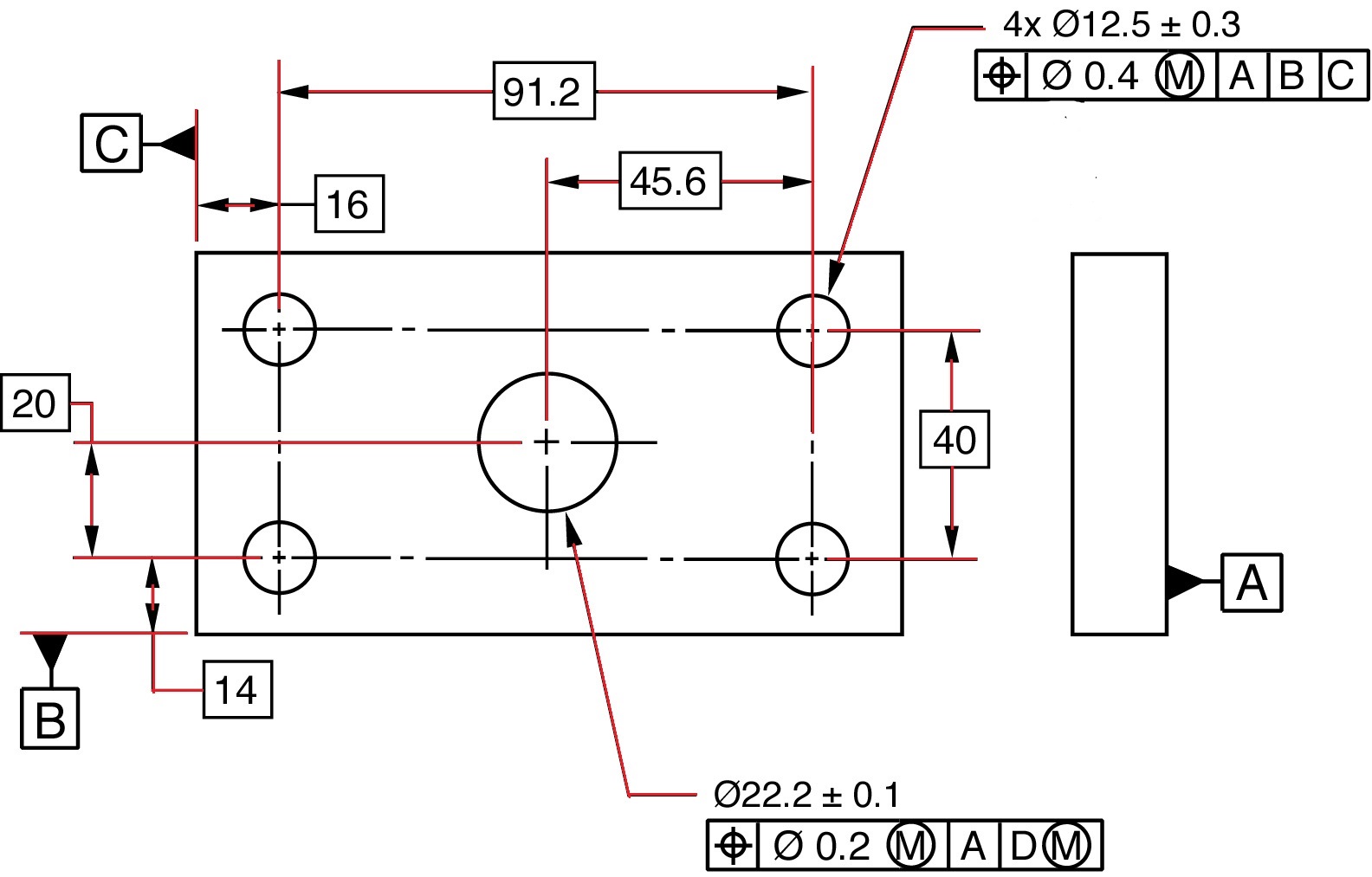
Web engineering drawing abbreviations and symbols are used to communicate and detail the. Web any engineering drawing should show everything: The ø stands for “diameter”. Dimensioning of part drawings 1. Plus and minus dimension — the allowable positive and negative variance from the specified dimension. Web an engineering drawing is a subcategory of technical drawings. Web dimensions in engineering drawings are numerical values indicated graphically in a proper unit of measurement on engineering drawing with lines, symbols, and notes.
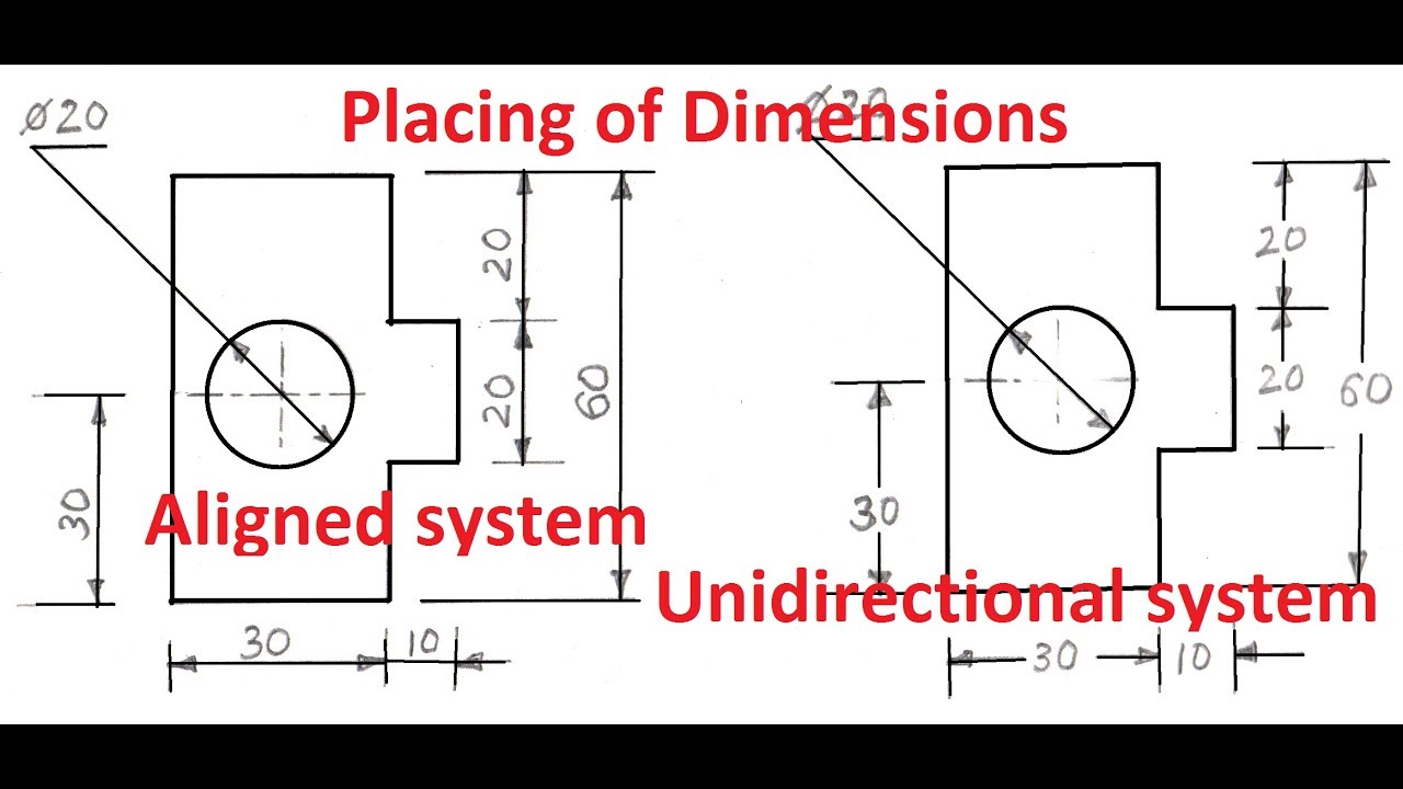
1.4aPlacing of Dimension Systems in Engineering Drawing Aligned and
Web the basic components of an engineering drawing are: Web simple holes are shown on engineering drawings by stating the diameter and the depth of the hole. Web ansi standard us engineering drawing sizes: Once the shape of a part is defined with an orthographic drawings, the size information is added also in the form.
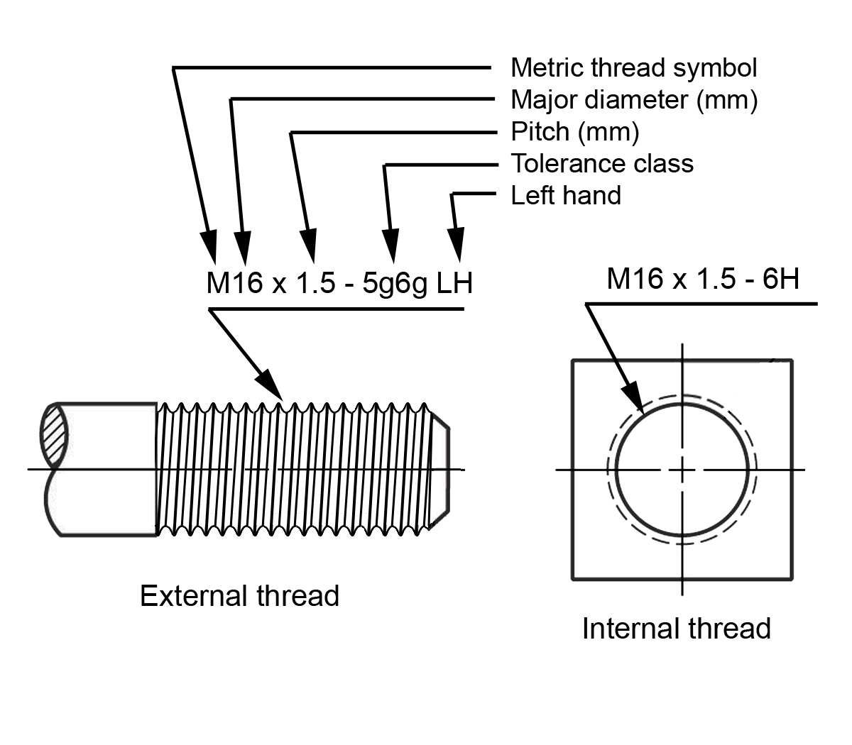
Dimensioning threaded fasteners Engineering Design McGill University
Web engineering drawing abbreviations and symbols are used to communicate and detail the. It is a system of symbols and standards used by engineers to provide manufacturing information to the production team. Drawing dimensions are expressed as numeric constants. The reasons for using geometric dimensioning and tolerancing (gd&t) are: Plus and minus dimension — the.

GD&T Blog Geometric Learning Systems
One can pack a great deal of information into an isometric drawing. Holes that go all the way through the component are known as through holes. Web limits of size — the largest acceptable size and the minimum acceptable size of a feature. You can also hide the dimension value and display. An engineering (or.
info Trade Engineering Drawing Important Notes
Dimensioning geometrics is the science of specifying and tolerancing the shapes and locations of features on objects. Dimensions are required for points, lines, and surfaces that are related functionally or control relationship of other features. Rationality of part dimensions 2. Holes that go all the way through the component are known as through holes. Basic.
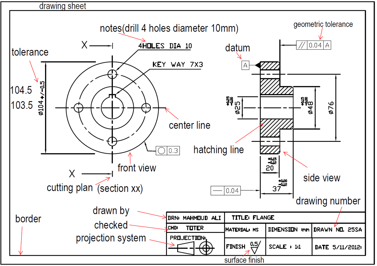
PPT BASIC ENGINEERING DRAWING PowerPoint Presentation, free download
It is a system of symbols and standards used by engineers to provide manufacturing information to the production team. Width (in) length (in) horizontal zone: This makes understanding the drawings simple with little to no personal interpretation possibilities. You add drawing dimensions as annotations to drawing views or geometry in drawing sketches. Dimensioning of part.

Solved Drawing automated diameter dimensions Autodesk Community
The ø stands for “diameter”. Web drawing dimensions are added to a drawing to further document the model, without changing or controlling features or part size. These are indicated on the engineering drawing to define the size characteristics such as length, height, breadth, diameter, radius, angle, etc. Web any engineering drawing should show everything: Web.
Types Of Dimensions In Engineering Drawing at GetDrawings Free download
It ensures that mating parts fit together well the universal language works regardless of who you are working with Rationality of part dimensions 2. It is indicated by arrowheads, it is drawn parallel to the surface whose length must be indicated. The bureau of indian standards (bis. A complete understanding of the object should be.

Lecture Notes Engineering Drawing Part 4
Web engineering drawing abbreviations and symbols are used to communicate and detail the. Dimensions are required for points, lines, and surfaces that are related functionally or control relationship of other features. The purpose is to convey all the information necessary for manufacturing a product or a part. Web limits of size — the largest acceptable.

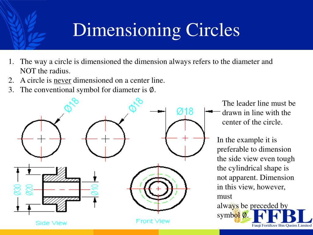
Dimensioning
The bureau of indian standards (bis. The ø stands for “diameter”. The reasons for using geometric dimensioning and tolerancing (gd&t) are: Width (in) length (in) horizontal zone: Web introduction dimensioning refers to the addition of size values to drawing entities. Dimensioning geometrics is the science of specifying and tolerancing the shapes and locations of features.
Design Tech Academy (3) GD&T Symbols Diameter, Radius, Controlled
A common use is to specify the geometry necessary for the construction of a component and is called a detail drawing. You add drawing dimensions as annotations to drawing views or geometry in drawing sketches. Web an engineering drawing is a subcategory of technical drawings. Web standard us engineering drawing sizes according ansi/asme y14.1 decimal.
Diameter Engineering Drawing You add drawing dimensions as annotations to drawing views or geometry in drawing sketches. The reasons for using geometric dimensioning and tolerancing (gd&t) are: Web introduction dimensioning refers to the addition of size values to drawing entities. It helps to define the requirements of an engineering part and conveys the. Web what is gd&t?
Web Engineering Drawings, Also Known As Mechanical Drawings, Manufacturing Blueprints, Drawings, Etc., Are Technical Drawings That Show The Shape, Structure, Dimensions, Tolerances, Accuracy, And Other Requirements Of A Part In The Form Of A Plan.
The reasons for using geometric dimensioning and tolerancing (gd&t) are: Web engineering drawing abbreviations and symbols are used to communicate and detail the. Web graphics communications are used in every phase of engineering design starting from concept illustration all the way to the manufacturing phase. One can pack a great deal of information into an isometric drawing.
Diameter Symbol — A Symbol Indicating.
These are indicated on the engineering drawing to define the size characteristics such as length, height, breadth, diameter, radius, angle, etc. Methods and steps for dimensioning parts 3. Engineering drawings use standardised language and symbols. An engineering (or technical) drawingis a graphical representation of a part, assembly, system, or structure and it can be produced using freehand, mechanical tools, or computer methods.
Width (In) Length (In) Horizontal Zone:
Precautions for dimensioning basic requirements for dimensioning in part drawings the dimensions in the part drawing shall be marked in accordance with the standard, complete, clear and reasonable. Web the process of adding size information to a drawing is known as dimensioning the drawing. Even when the shaft is at its minimum diameter and the hole at its largest. Plus and minus dimension — the allowable positive and negative variance from the specified dimension.
This Makes Understanding The Drawings Simple With Little To No Personal Interpretation Possibilities.
Dimensioning geometrics is the science of specifying and tolerancing the shapes and locations of features on objects. A common use is to specify the geometry necessary for the construction of a component and is called a detail drawing. Web an engineering drawing is a subcategory of technical drawings. For example, a 20 diameter hole that goes straight through the component would be represented as “ø20 through”.