Chamfer Drawing Callout
Chamfer Drawing Callout - Web you can dimension chamfers in drawings. If appropriate, add stacked text in the note. When threads are rolled, the angle on the first and last threads may approximate a 45° angle. Use rapid dimensioning to place evenly spaced dimensions. Then select one of the lines at the end of your chamfer, then select the line of the edge of the chamfer.
Basic dimensioning is the addition of only functional size values to drawing entities. Web you can dimension chamfers in drawings. Dimensions are required for points, lines, and surfaces that are related functionally or control relationship of other features. Select a circle that is part of a hole feature, or a thread that is part of an external thread feature. Web to make the dimension callout like your picture, select the perpindicular option on the chamfer dimensioning tool dropdown menu. Solidwork has a dimension style that is c1 for 45 degree chamfers. In the conclusion, it will point out chamfering best practices.
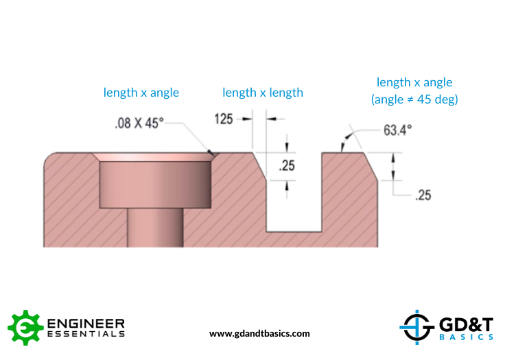
Chamfer Dimensioning GD&T Basics
Select the first chamfer reference, such as a point on a model edge or draft entity. Ensure that you select a point close to the desired start point of the chamfer, as your selection point determines the default angle. Web solidworks course for beginners: Dimensions are required for points, lines, and surfaces that are related.
Solved Multiple chamfers on drawings PTC Community
In addition to the usual dimension display properties, chamfer dimensions have their own options for leader display, text display, and x display. The select dialog box opens. Web you can dimension chamfers in drawings. Select a circle that is part of a hole feature, or a thread that is part of an external thread feature..
Adding a Chamfer Dimension YouTube
We will discuss how to measure it and how are chamfers dimensioned. What is the correct way to call out a 45 degree chamfer? Web if you created the chamfer using the chamfer feature, simply show your dimensions for that feature or view. So that i could change it to standard leader option ? Web.
Dimensioning Chamfers YouTube
If the selection was part of a hole feature, the precision, tolerance, fit class tolerance, and shaft class tolerance values from that feature are automatically applied. Mechanical engineer sw2005 sp 4.0 & pro/e 2001 dell precision 370 p4 3.6 ghz, 1gb. Then select one of the lines at the end of your chamfer, then select.
AutoCAD Tutorial Using the CHAMFER Command YouTube
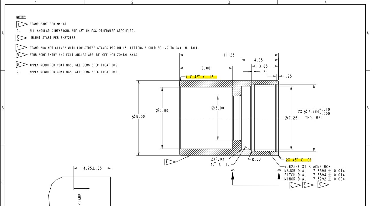
Is the correct callout for this 2x 0.031 x 45° or does each chamfer need to be noted individually? Click on the links below to learn more about each gd&t symbol or concept, and be sure to download the free wall chart for a quick reference when at your desk or on the shop floor..
Dimensioning standards
X display is the size of the x in a chamfer dimension with two numbers, such as 1 x 45° (length x angle), 45° x 1 (angle x length), 1 x 1 (length x length) or. In the edit chamfer note dialog box, click in the edit box to add, delete, or edit text. The.
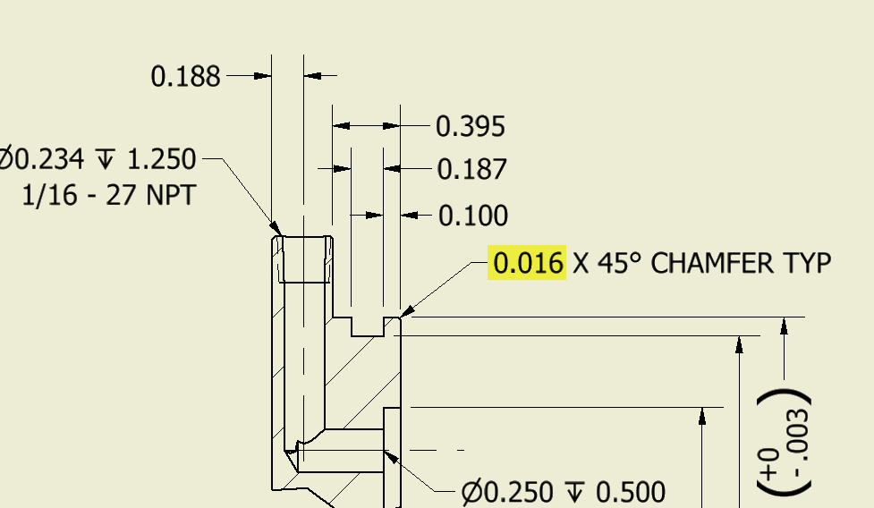
Inventor Ability to change the decimal places in the call out of the
Mechanical engineer sw2005 sp 4.0 & pro/e 2001 dell precision 370 p4 3.6 ghz, 1gb. See figure 2 for chamfer dimensioning examples. Ewh (aerospace) 19 jul 06 11:18 Web a convenient guide for geometric dimensioning and tolerancing (gd&t) symbols at your fingertips. Web chamfer call out. Web a chamfer callout on this platform is straightforward.
Introduction to AutoCAD Chamfer YouTube
Web a convenient guide for geometric dimensioning and tolerancing (gd&t) symbols at your fingertips. Then select the edges, features, or faces to chamfer. If an angle other than 45 degrees is dimensioned, the surface to which the angle is measured must be made clear on the drawing. Exact angles can not be produced due to.
Drawing Dimension chamfer note tool Autodesk Community
If an angle other than 45 degrees is dimensioned, the surface to which the angle is measured must be made clear on the drawing. In addition to the usual dimension display properties, chamfer dimensions have their own options for leader display, text display, and x display. The symbol x could be the meaning of times.
Dimension Guidelines ViBaDirect
Then select the edges, features, or faces to chamfer. Ewh (aerospace) 19 jul 06 11:18 Web to make the dimension callout like your picture, select the perpindicular option on the chamfer dimensioning tool dropdown menu. In the edit chamfer note dialog box, click in the edit box to add, delete, or edit text. Web solidworks.
Chamfer Drawing Callout Types, dimensions & callout this guide will help you to understand what is a chamfer and point out some differences. You can also click legacy sketch > chamfer. See figure 2 for chamfer dimensioning examples. Dimensions are required for points, lines, and surfaces that are related functionally or control relationship of other features. Web what is the standard for a callout of a chamfer feature?
Is There A Way To Change It ?
You can also click legacy sketch > chamfer. Types, dimensions & callout this guide will help you to understand what is a chamfer and point out some differences. If an angle other than 45 degrees is dimensioned, the surface to which the angle is measured must be made clear on the drawing. You can edit a chamfer note to change its content or format.
Select A Circle That Is Part Of A Hole Feature, Or A Thread That Is Part Of An External Thread Feature.
Is the correct callout for this 2x 0.031 x 45° or does each chamfer need to be noted individually? If no angle is given the chamfer is assumed to be at 45 degrees. Y14.5 clearly says a note 1 x 1 or 1 x 45° is allowed. 3 x 3 or 3 x 45° (not this 3x3 or 3x45°), for a repeated feature, the word times is implied, a space must follow the x symbol only (no space.
In Addition To The Usual Dimension Display Properties, Chamfer Dimensions Have Their Own Options For Leader Display, Text Display, And X Display.
Web 19 jul 06 11:03 when using a leader to call out a chamfer (ie. Web to make the dimension callout like your picture, select the perpindicular option on the chamfer dimensioning tool dropdown menu. Web solidworks course for beginners: Ewh (aerospace) 19 jul 06 11:18
Web 26 Sep 05 14:51 I Have A Cylindrical Part With A Chamfer At Each End.
The symbol x could be the meaning of times or by. .040 x 30) to my knowledge the.040 be the depth into the material and the 30 degrees is the angle from the centerline. In the conclusion, it will point out chamfering best practices. So that i could change it to standard leader option ?


