
Chamfer Callout On Drawing
Chamfer Callout On Drawing - Is there a way to change it ? Break edge note example break edge note example how to make a break edge break edge on. Solidwork has a dimension style that is c1 for 45 degree chamfers. Web dimensioning chamfers is done with a call out that specifies the length of the chamfer along with the angle of the chamfer. And i think it`s quite similar in ansi too.
Web to make the dimension callout like your picture, select the perpindicular option on the chamfer dimensioning tool dropdown menu. All of the basic components of an engineering drawing are detailed below with links throughout to. If the selection was part of a hole feature, the precision, tolerance, fit class tolerance, and shaft class tolerance values from that feature are automatically applied. Then select the edges, features, or faces to chamfer. The dimensioning of the chamfer is very simple on technical drawings. This method means you get a chamfer. Basic dimensioning is the addition of only functional size values to drawing entities.

Steps to add chamfer dimension in 2D drawing SEACAD
Exact angles can not be produced due to the displacement of the metal forming the thread. Then select the edges, features, or faces to chamfer. Break edge note example break edge note example how to make a break edge break edge on. Is the correct callout for this 2x 0.031 x 45° or does each.
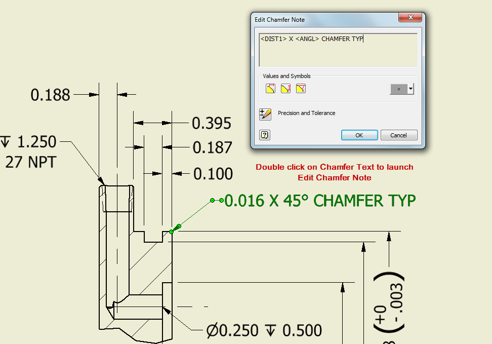
Inventor Ability to change the decimal places in the call out of the
There are two schools of thought on whether a chamfer and. This method means you get a chamfer. Click chamfer dimension on the dimensions/relations toolbar or click tools > dimensions > chamfer. In addition to the usual dimension display properties, chamfer dimensions have their own options for leader display, text display, and x display. Then.
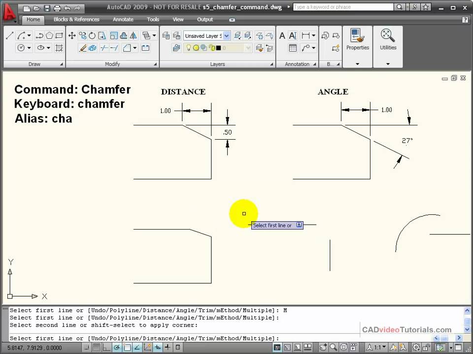
AutoCAD Tutorial Using the CHAMFER Command YouTube
Web jan 17, 2017 03:23 pm when i create a shown dimension for a chamfer in a drawing the leader seem to be fixed to an angle or its created with the normal leader option. Web apr 19, 2016 03:45 pm. When threads are rolled, the angle on the first and last threads may approximate.
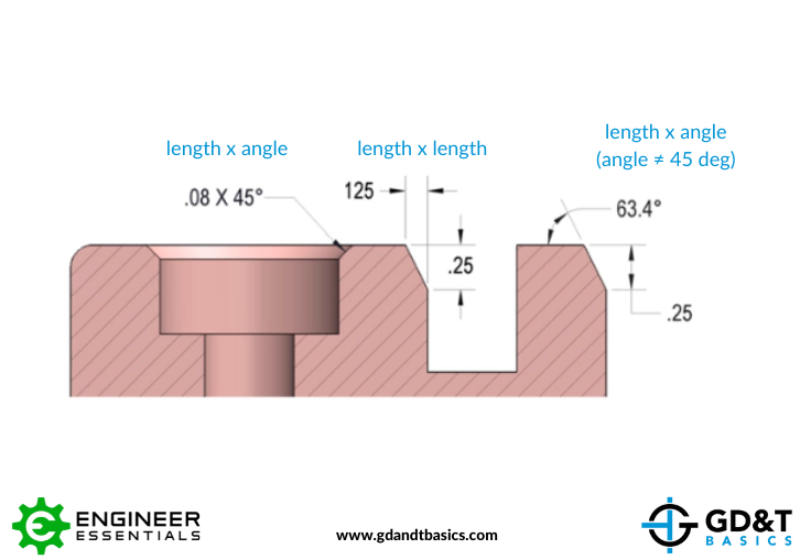
Chamfer Dimensioning GD&T Basics
Ewh (aerospace) 19 jul 06 11:18 Exact angles can not be produced due to the displacement of the metal forming the thread. Then select one of the lines at the end of your chamfer, then select the line of the edge of the chamfer. You specify a chamfer callout when you want a chamfer, and.
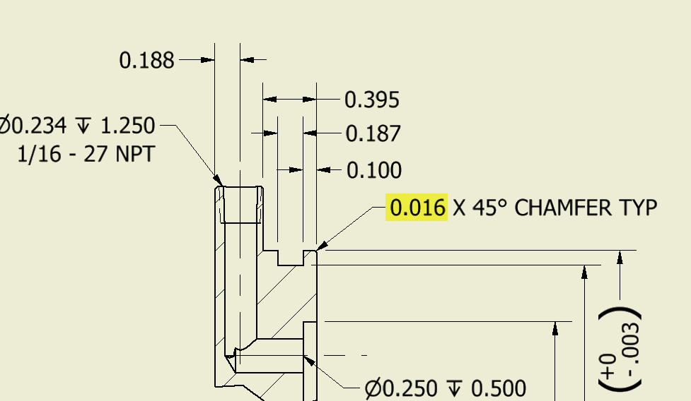
Inventor Ability to change the decimal places in the call out of the
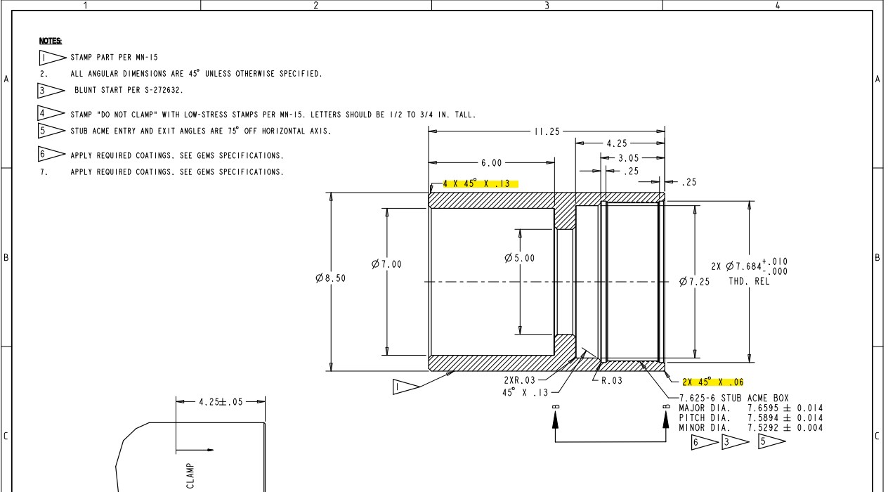
4x 3 x 45deg seems a bit confusing. Web when dimensioning a chamfer on a parts drawing, according to iso, one has to show the height of the chamfer and the angle of the chamfer (e.g 0,3x45°). Is the correct callout for this 2x 0.031 x 45° or does each chamfer need to be noted.
Solved Multiple chamfers on drawings PTC Community
Then select one of the lines at the end of your chamfer, then select the line of the edge of the chamfer. Style 0 kudos reply notify moderator After drawing the part, from the menu bar select design > solid > modify > chamfer. You specify a chamfer callout when you want a chamfer, and.
Dimensioning standards
There are two schools of thought on whether a chamfer and. They are created as slopes at the end of the round mechanical elements. Basic dimensioning is the addition of only functional size values to drawing entities. Mechanical engineer sw2005 sp 4.0 & pro/e 2001 dell precision 370 p4 3.6 ghz, 1gb. Style 0 kudos.

How to interpret the values of a chamfer and a thread in a blueprint
Web if you have multiples of.06 and.13 chamfers, is the drawing at a scale where they can be easily distinguished? Exact angles can not be produced due to the displacement of the metal forming the thread. This opens the chamfer dialog box. Solidwork has a dimension style that is c1 for 45 degree chamfers. You.

SolidWorks Tutorial How to Add Chamfer Dimension In Solidworks Drawing
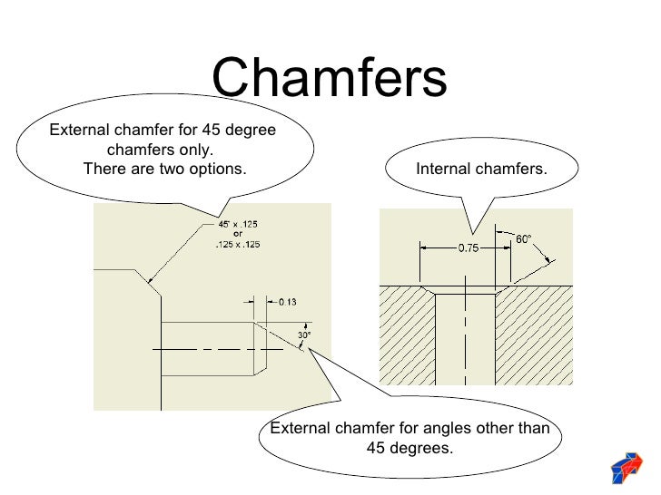
Chamfers can be dimensioned in two ways, either by calling out the length by angle, or calling out the length by length. Go to the annotate tab, select the show model annotations icon, make sure dimension is selected in the pop up and select the chamfer, it will show your dimension. I have been using.

Adding a Chamfer Dimension YouTube
There are two schools of thought on whether a chamfer and. Web if you have multiples of.06 and.13 chamfers, is the drawing at a scale where they can be easily distinguished? Thread relief and chamfers threads up to a shoulder or in a blind hole present the same. Mechanical engineer sw2005 sp 4.0 & pro/e.
Chamfer Callout On Drawing If 2x is specified, is there more than one position which could be the second chamfer? After drawing the part, from the menu bar select design > solid > modify > chamfer. Web dimensioning chamfers is done with a call out that specifies the length of the chamfer along with the angle of the chamfer. This opens the chamfer dialog box. I have been using this style for many years with multiple companies and drafting programs and have never questioned it.
You Can Dimension Chamfers In Drawings.
.040 x 30) to my knowledge the.040 be the depth into the material and the 30 degrees is the angle from the centerline. You just need to give the length of one edge and the corresponding angle to it. 4x r5, or r5 4x? You specify a chamfer callout when you want a chamfer, and only a chamfer.
Is It To Call Out The Note With A Leader (.25 X 45°) Or To Add Two Seperate Dimensions (One Linear And Chamfer Callout?
From the chamfer dialog box, select the. Is the correct callout for this 2x 0.031 x 45° or does each chamfer need to be noted individually? In addition to the usual dimension display properties, chamfer dimensions have their own options for leader display, text display, and x display. Web to insert chamfer dimensions into a drawing:
Web Break Edge Callouts Are Specified Directly On The Drawing To Reference A Certain Surface Or As A Note E.g.
Select a circle that is part of a hole feature, or a thread that is part of an external thread feature. Then select the edges, features, or faces to chamfer. If 2x is specified, is there more than one position which could be the second chamfer? See figure 2 for chamfer dimensioning examples.
Ewh (Aerospace) 19 Jul 06 11:18
When threads are rolled, the angle on the first and last threads may approximate a 45° angle. There are two schools of thought on whether a chamfer and. Is there a way to change it ? I have been using this style for many years with multiple companies and drafting programs and have never questioned it.