
Chamfer Callout Drawing
Chamfer Callout Drawing - Web what is the standard for a callout of a chamfer feature? Web to insert chamfer dimensions into a drawing: Web basic dimensioning introduction dimensioning refers to the addition of size values to drawing entities. 4x r5, or r5 4x? That’s why we’ve broken down the process into bite size chunks.
If you created the chamfer using the chamfer feature, simply show your dimensions for that feature or view. Web since threading often produces starting burrs, these can be minimized by specifying a 45° countersink or chamfer which is.015″ minimum larger than the major diameter on internal threads (see figure 4) and.015″ minimum smaller than the minor diameter on external threads (see figure 3). For structural i have previously. You just need to give the length of one edge and the corresponding angle to it. Mechanical engineer sw2005 sp 4.0 & pro/e 2001 dell precision 370 p4 3.6 ghz, 1gb. You must select the chamfered edge first. That’s why we’ve broken down the process into bite size chunks.
Chamfer Dimensioning GD&T Basics
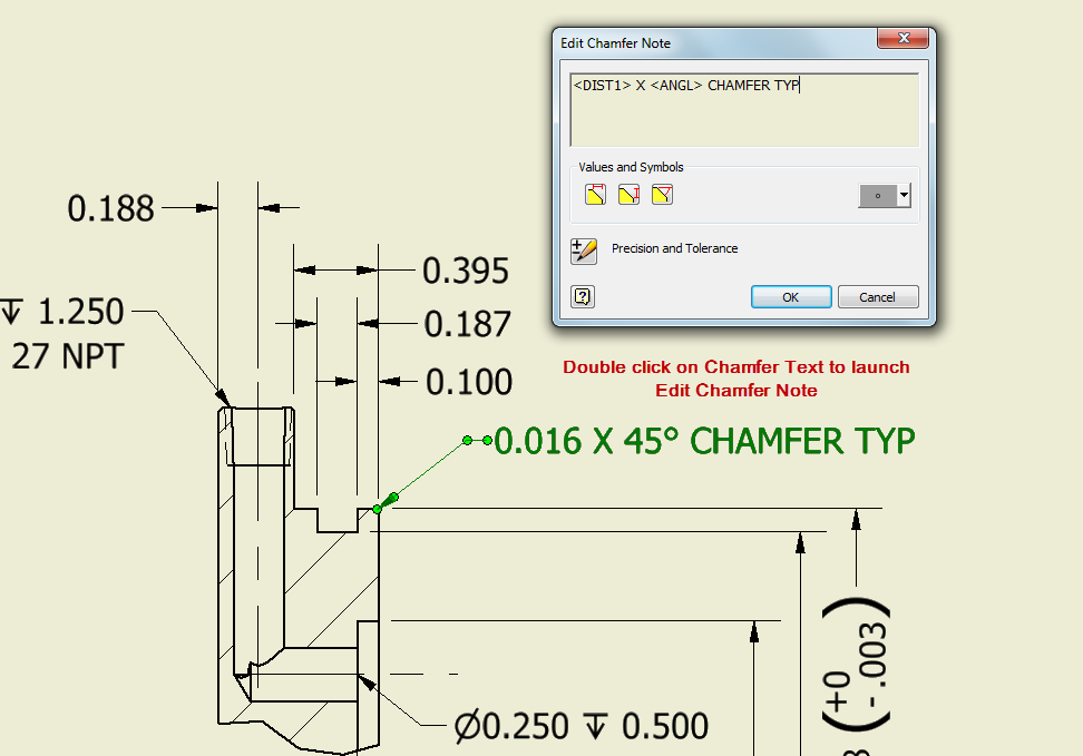
After drawing the part, from the menu bar select design > solid > modify > chamfer. Is it to call out the note with a leader (.25 x 45°) or to add two seperate dimensions (one linear and chamfer callout? Web apr 19, 2016 03:45 pm. Web the dimensioning of the chamfer is very simple.
Solved Multiple chamfers on drawings PTC Community
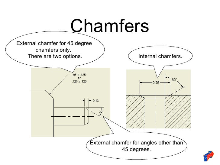
Ewh (aerospace) 19 jul 06 11:18 Web may 5, 2022 by brandon fowler learning to read blueprints can be hard. If an angle other than 45 degrees is dimensioned, the surface to which the angle is measured must be made clear on the drawing. This opens the chamfer dialog box. Select a circle that is.

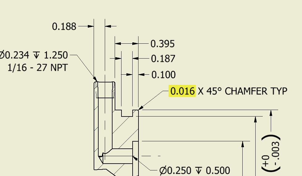
How to interpret the values of a chamfer and a thread in a blueprint
If you created the chamfer using the chamfer feature, simply show your dimensions for that feature or view. Then select the edges, features, or faces to chamfer. There are two schools of thought on whether a chamfer and. 4x r5, or r5 4x? Also, if you have multiple fillets, which format would be correct? Ensure.
Inventor Ability to change the decimal places in the call out of the
Web break edge callouts are specified directly on the drawing to reference a certain surface or as a note e.g. The select dialog box opens. Web to insert chamfer dimensions into a drawing: Web basic dimensioning introduction dimensioning refers to the addition of size values to drawing entities. If the selection was part of a.
Dimensioning standards
That should result in what you have shown. Web to make the dimension callout like your picture, select the perpindicular option on the chamfer dimensioning tool dropdown menu. Drag to place the callout. Web since threading often produces starting burrs, these can be minimized by specifying a 45° countersink or chamfer which is.015″ minimum larger.
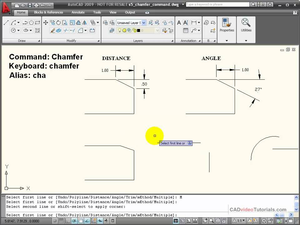
AutoCAD Tutorial Using the CHAMFER Command YouTube
If machinery has screw holes or screws they must be dimensioned properly. Web a chamfer callout on this platform is straightforward with the steps as follows: Drag to place the callout. Break edge note example break edge note example how to make a break edge break edge on. After drawing the part, from the menu.
Inventor Ability to change the decimal places in the call out of the
.040 x 30) to my knowledge the.040 be the depth into the material and the 30 degrees is the angle from the centerline. Web to make the dimension callout like your picture, select the perpindicular option on the chamfer dimensioning tool dropdown menu. Web apr 19, 2016 03:45 pm. 4x 3 x 45deg seems a.

Dimensioning Chamfers YouTube
There are two schools of thought on whether a chamfer and. Ensure that you select a point close to the desired start point of the chamfer, as your selection point determines the default angle. Chamfers can also be specified. Ewh (aerospace) 19 jul 06 11:18 .040 x 30) to my knowledge the.040 be the depth.

SolidWorks Tutorial How to Add Chamfer Dimension In Solidworks Drawing
Web may 5, 2022 by brandon fowler learning to read blueprints can be hard. Then select the edges, features, or faces to chamfer. That’s why we’ve broken down the process into bite size chunks. Break edge note example break edge note example how to make a break edge break edge on. You must select the.

Adding a Chamfer Dimension YouTube
Then select the edges, features, or faces to chamfer. To continue from the aforementioned thread, how would i call out multiple chamfered corners? Web since threading often produces starting burrs, these can be minimized by specifying a 45° countersink or chamfer which is.015″ minimum larger than the major diameter on internal threads (see figure 4).
Chamfer Callout Drawing Break edge note example break edge note example how to make a break edge break edge on. For structural i have previously. Select a circle that is part of a hole feature, or a thread that is part of an external thread feature. 4x r5, or r5 4x? Web have you ever seen a 1x1 chamfer called out as c1 on a drawing?
Basic Dimensioning Is The Addition Of Only Functional Size Values To Drawing Entities.
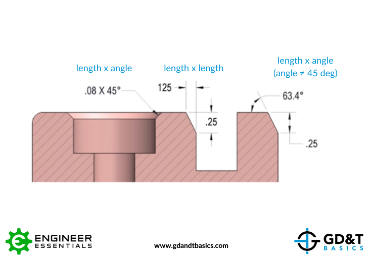
Web have you ever seen a 1x1 chamfer called out as c1 on a drawing? Web apr 19, 2016 03:45 pm. Web dimensioning chamfers is done with a call out that specifies the length of the chamfer along with the angle of the chamfer. If an angle other than 45 degrees is dimensioned, the surface to which the angle is measured must be made clear on the drawing.
Then Select One Of The Lines At The End Of Your Chamfer, Then Select The Line Of The Edge Of The Chamfer.
Also, if you have multiple fillets, which format would be correct? Web a chamfer callout on this platform is straightforward with the steps as follows: Drag to place the callout. Break edge note example break edge note example how to make a break edge break edge on.
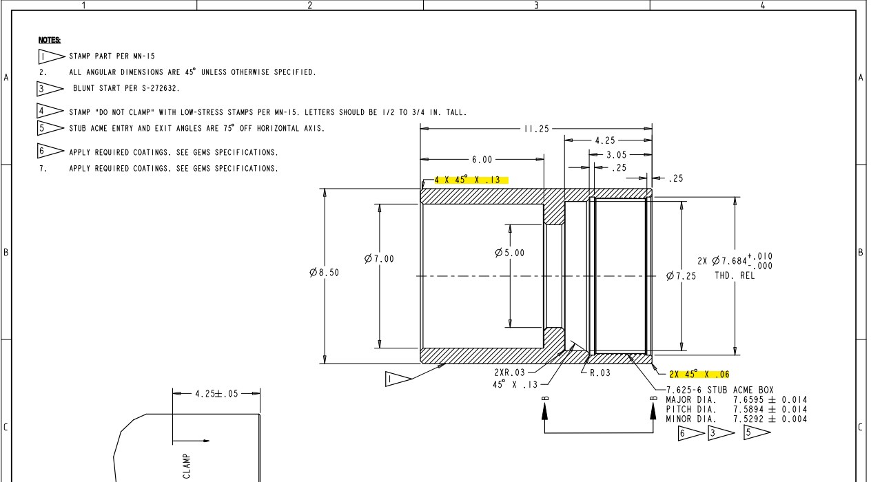
Web Since Threading Often Produces Starting Burrs, These Can Be Minimized By Specifying A 45° Countersink Or Chamfer Which Is.015″ Minimum Larger Than The Major Diameter On Internal Threads (See Figure 4) And.015″ Minimum Smaller Than The Minor Diameter On External Threads (See Figure 3).
Chamfers can also be specified. Web to insert chamfer dimensions into a drawing: Ensure that you select a point close to the desired start point of the chamfer, as your selection point determines the default angle. At times, the break edge specification may be contained in the general tolerance block such as shown below.
Dimensions Are Required For Points, Lines, And Surfaces That Are Related Functionally Or Control Relationship Of Other Features.
After drawing the part, from the menu bar select design > solid > modify > chamfer. See figure 2 for chamfer dimensioning examples. Is it to call out the note with a leader (.25 x 45°) or to add two seperate dimensions (one linear and chamfer callout? To continue from the aforementioned thread, how would i call out multiple chamfered corners?