
Break Lines In Engineering Drawing
Break Lines In Engineering Drawing - Web 18.06.2020 by andreas velling engineering drawing basics explained an engineering drawing is a subcategory of technical drawings. Engineering drawings use standardised language and symbols. Section line a section line is a.7 mm to.9 mm line drawn at angles, normally 45, 30 or 60 degrees, to show a feature more clearly. Break lines are used to separate sections for clarity or to shorten a section. Section lines (hatching) are used in section views to represent surfaces of an object cut by a cutting plane.
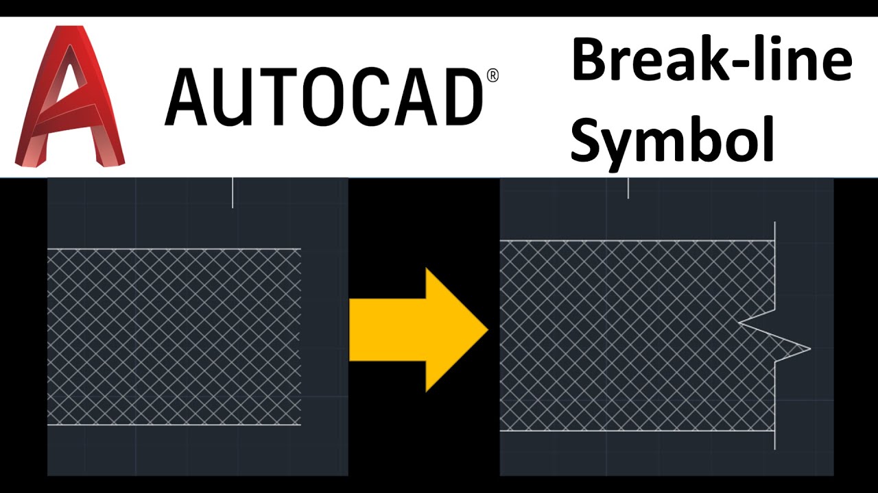
Web there are three kinds of break lines used in drawings. Engineering drawings use standardised language and symbols. Continuous thin zigzag line this line is used to show long break. Web break lines are drawn to show that a part has been shortened to reduce its size on the. Section view to represent the internal details of an assembly or. They are used to remove, or ‘break out” part of a drawing for clarity, and also to shorten objects which have the same shape throughout their length and may be too long to place on the drawing. Line characteristics, such as widths, breaks in the line, and zigzags, all have definite meanings.

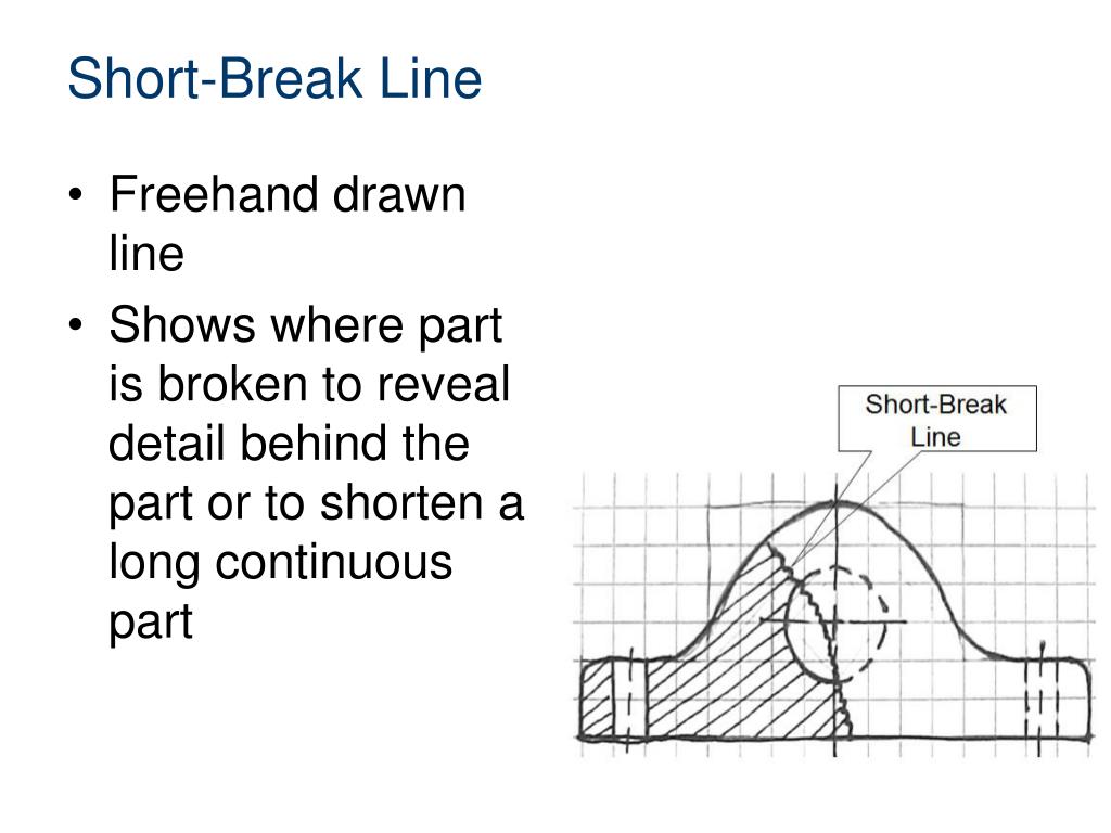
short break line example
Web engineering lines can be classified into several categories based on their purpose and representation. Engineering drawings come in many forms. The edge of the partial or interrupted. It is more than simply a drawing, it is a graphical language that communicates ideas and information. Why not just use a 3d model? Hidden lined (thick).
AUTOCAD 2020 BREAKLINE SYMBOL HOW TO DRAW BREAK LINE SYMBOL YouTube
Web freehand lines shows breaks or cuts in parts or assemblies. In this highly interactive object, learners associate basic line types and terms with engineering drawing geometry. Web engineering drawings (aka blueprints, prints, drawings, mechanical drawings) are a rich and specific outline that shows all the information and requirements needed to manufacture an item or.
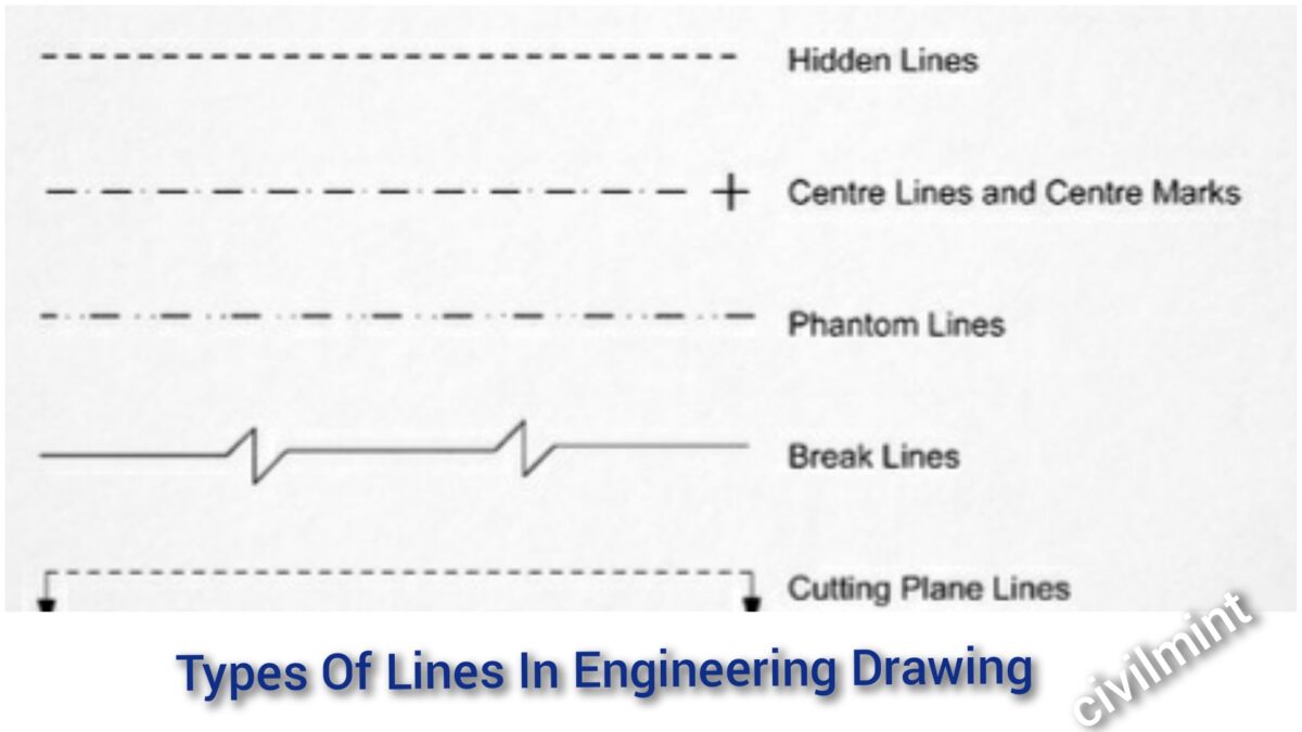
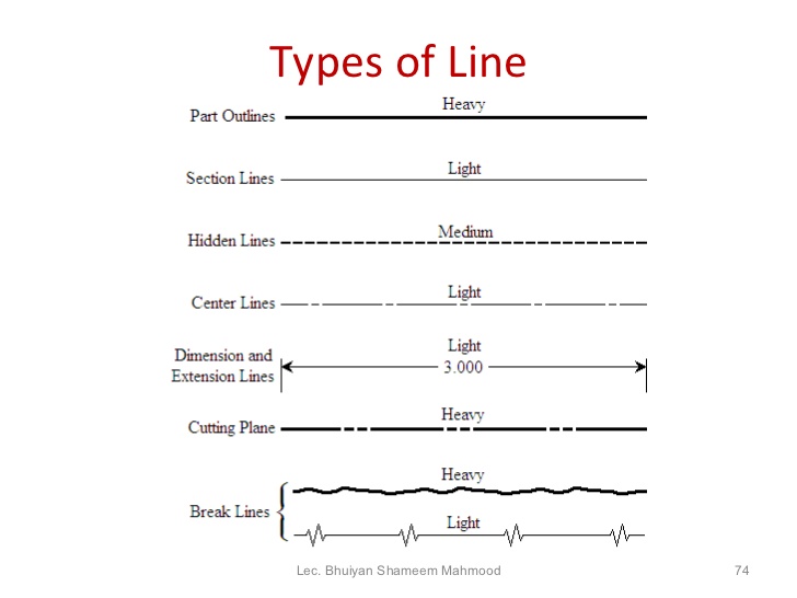
Line Conventions
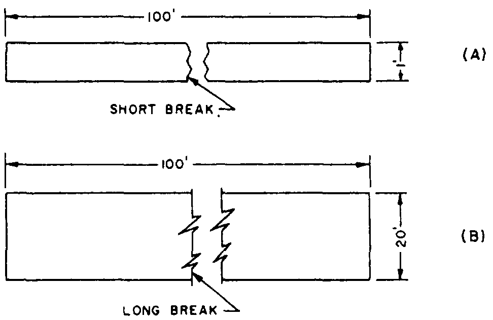
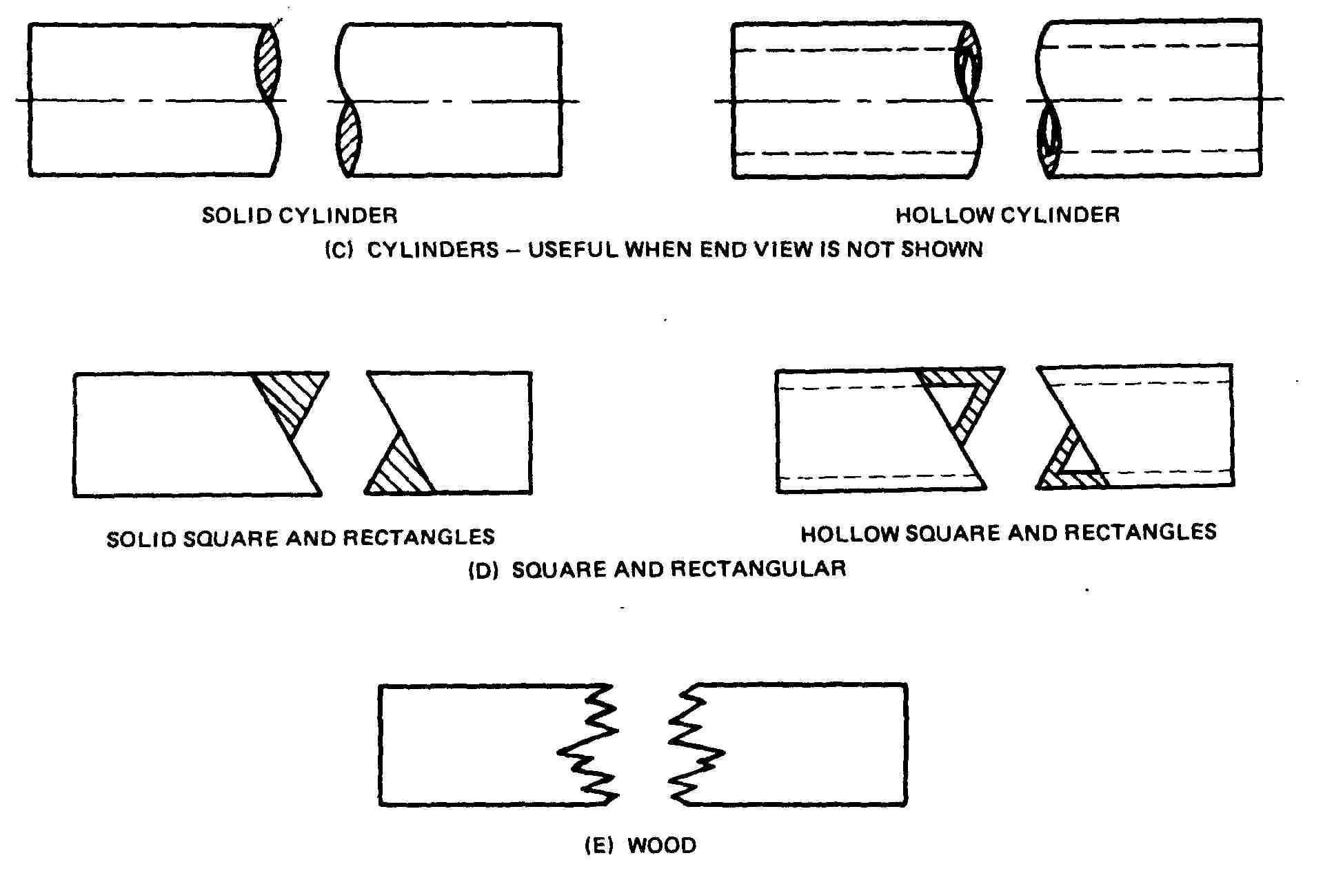
There are three types of break lines, each with a distinct line weight: Suppose, for example,you want to make a drawing of a rectangle 1 ftwide by 100 ft long to the scale of 1/12, or1 in. Web 18.06.2020 by andreas velling engineering drawing basics explained an engineering drawing is a subcategory of technical drawings..
Types Of Lines In Engineering Drawing
Engineering drawings use standardised language and symbols. Section line a section line is a.7 mm to.9 mm line drawn at angles, normally 45, 30 or 60 degrees, to show a feature more clearly. Web this line is used to show short break or irregular boundaries. Let’s explore some of the most common types of lines.
short and long break lines
Web break lines are drawn to show that a part has been shortened to reduce its size on the. Web object lines (figure 3) are the most common lines used in drawings. A long, ruled thin line with zigzags. There are three types of break lines, each with a distinct line weight: A freehand thick.
Drawing terms on emaze
Web an engineering drawing is a drawing or a set of drawings that communicates an idea, design, schematic, or model. It is more than simply a drawing, it is a graphical language that communicates ideas and information. These thick, solid lines show the visible edges, corners, and surfaces of a part. They are used to.

Different Types of LINES in Engineering Drawing//Classification of
Engineering drawings use standardised language and symbols. Section line a section line is a.7 mm to.9 mm line drawn at angles, normally 45, 30 or 60 degrees, to show a feature more clearly. Dashed line this line is used to show hidden edges of the main object. Text is extended from this shoulder such that.
Engineering Drawing 8 Tips to Improve Engineering Drawing Skills
Long, thin lines are used as long break lines to indicate that the center section of an. Each engineering field has its own type of engineering drawings. There are three types of break lines, each with a distinct line weight: Engineering drawings come in many forms. These lines are drawn to represent hidden or invisible.

Engineering Drawing 2 Ch4 Conventional break YouTube
Web break lines are used to shorten the size of a view for an exceptionally long part. Web break lines come in two forms: The following is a detailed description of the above applications. Web published oct 15, 2023 + follow introduction to lines in engineering drawing lines in engineering drawing are more than just.

Classifications of Civil Engineering Drawings and Interpreting
Why not just use a 3d model? Web this line is used to show short break or irregular boundaries. Web break linesthe size of the graphic representation of anobject is often reduced (usually for the purposeof economizing on paper space) by the use of adevice called a break. Hidden lined (thick) hidden lined (thick) type.
Break Lines In Engineering Drawing Web published oct 15, 2023 + follow introduction to lines in engineering drawing lines in engineering drawing are more than just strokes on paper; Object lines stand out on the drawing and clearly define the outline and features of the object. Web 18.06.2020 by andreas velling engineering drawing basics explained an engineering drawing is a subcategory of technical drawings. Web there are three types of break lines, each with a distinct line weight: A freehand thick line, and.
Engineering Drawings Use Standardised Language And Symbols.
Web this line is used to show short break or irregular boundaries. Continuous thin zigzag line this line is used to show long break. These lines are drawn to represent hidden or invisible edges of the objects. Line characteristics, such as widths, breaks in the line, and zigzags, all have definite meanings.
Why Not Just Use A 3D Model?
Object lines stand out on the drawing and clearly define the outline and features of the object. Section lines (hatching) are used in section views to represent surfaces of an object cut by a cutting plane. Web break lines are used to shorten the size of a view for an exceptionally long part. Web engineering lines can be classified into several categories based on their purpose and representation.
Section Line A Section Line Is A.7 Mm To.9 Mm Line Drawn At Angles, Normally 45, 30 Or 60 Degrees, To Show A Feature More Clearly.
Web freehand lines shows breaks or cuts in parts or assemblies. For example, electrical engineers draw circuit schematics and circuit board layouts. Break lines are used to separate sections for clarity or to shorten a section. Web 18.06.2020 by andreas velling engineering drawing basics explained an engineering drawing is a subcategory of technical drawings.
The Following Is A Detailed Description Of The Above Applications.
Dimension and extension lines are used to indicate the sizes of features on a drawing. They are used to remove, or ‘break out” part of a drawing for clarity, and also to shorten objects which have the same shape throughout their length and may be too long to place on the drawing. Web basic types of lines used in engineering drawings by kelly curran glenn sokolowski. Short break lines are denoted by a thick wavy line and are used to break the edge or surface of a.