
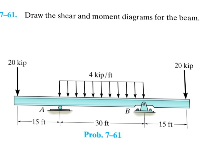
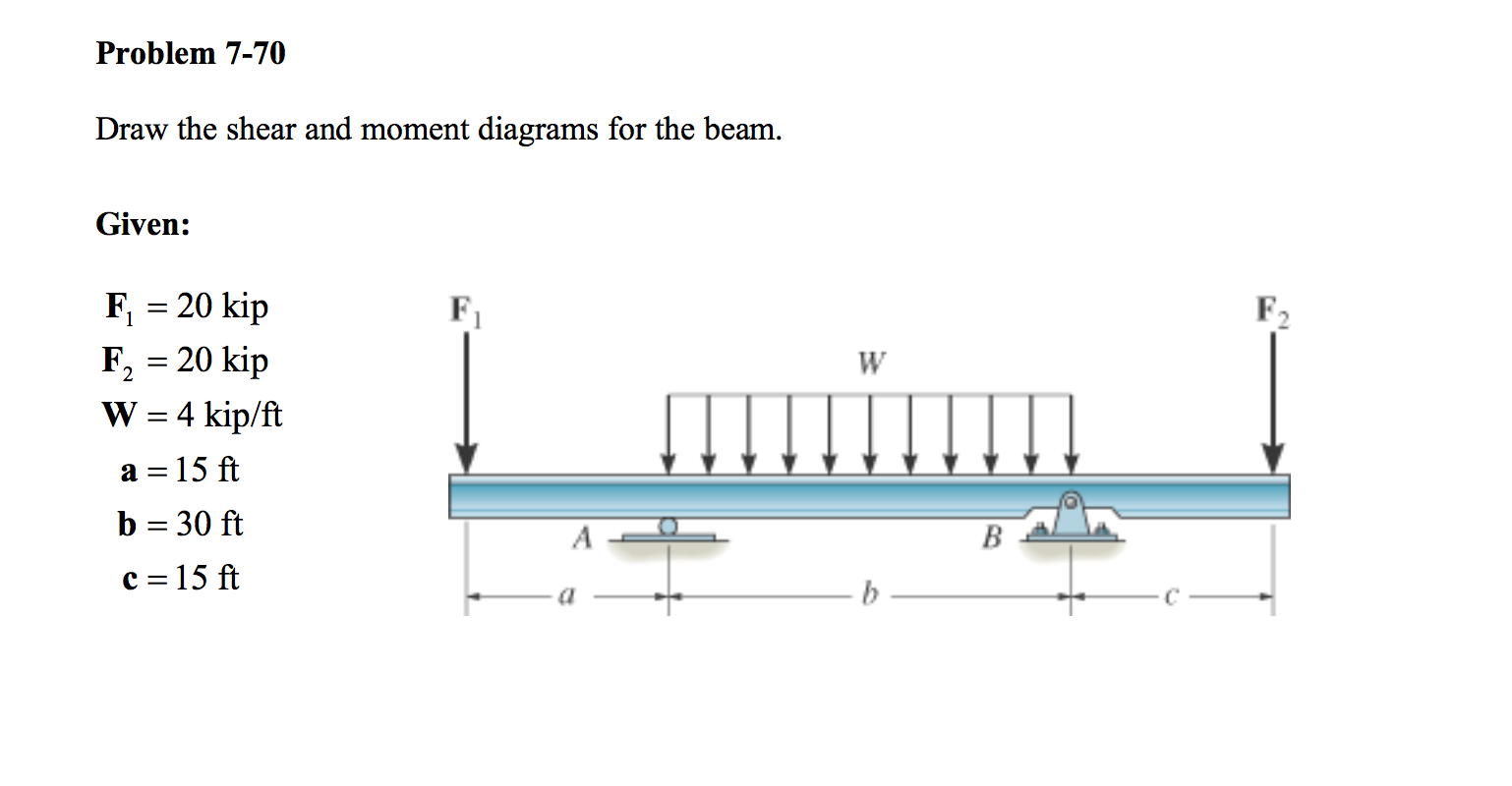
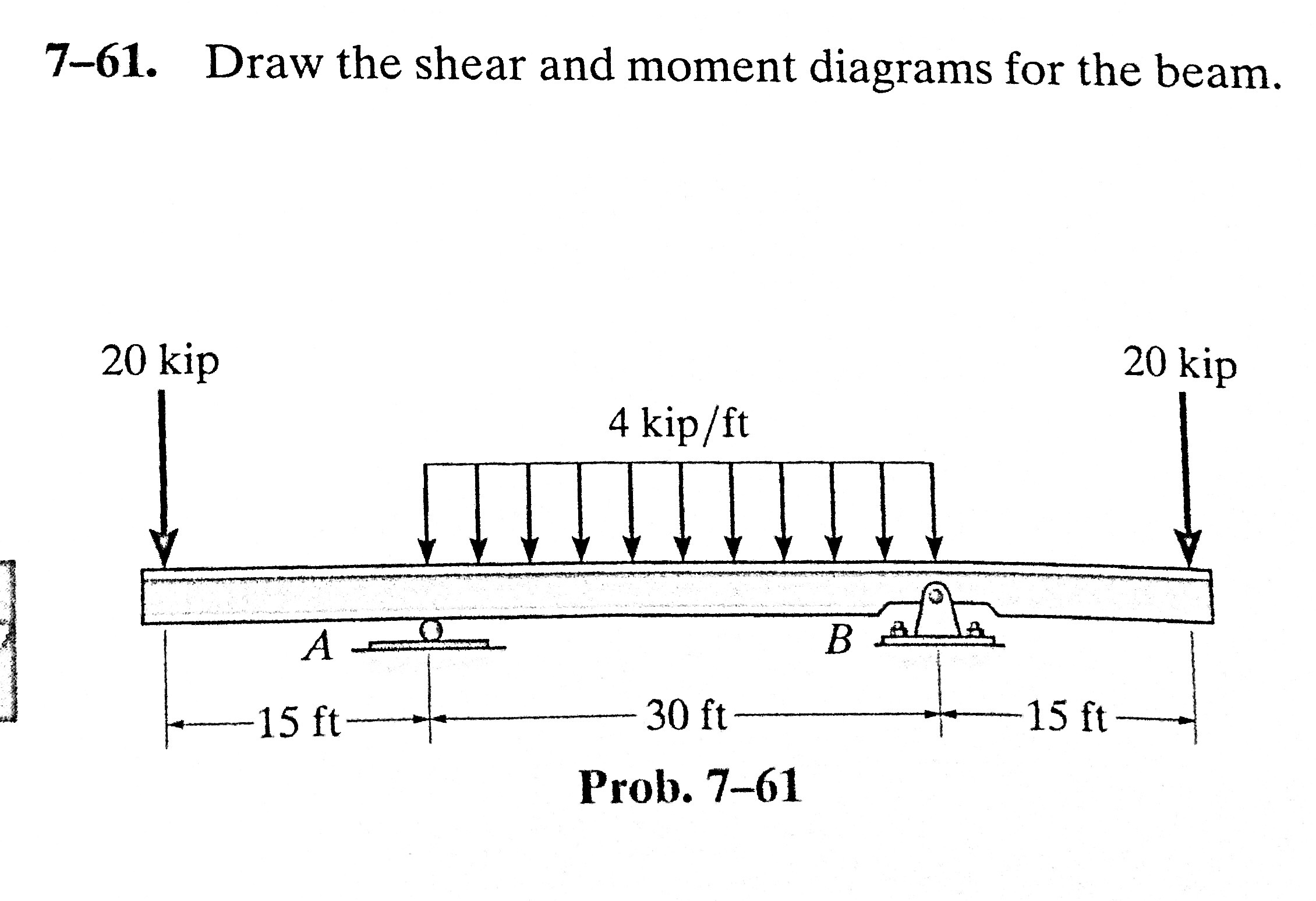
7-61 Draw The Shear And Moment Diagrams For The Beam
7-61 Draw The Shear And Moment Diagrams For The Beam - Web problem 7.61 part a draw the shear diagram for the beam. Normal stresses a beam subjected to a positive bending moment will tend to. 800 n 600 n 1200 n·m b 1 m 1 m 1 m 1 m prob. Web expert answer 100% (1 rating) transcribed image text: The vertical support reaction at a on.
Web draw the shear and moment diagrams for the beam. Web draw the shearing force and bending moment diagrams for the beam with an overhang subjected to the loads shown in figure 4.8a. The total load acting through the center of the infinitesimal length is wdx. The smooth pin is supported by two leaves a and b and subjected to a compressive load of 0 knm caused by bar c. Web expert answer 100% (1 rating) transcribed image text: Web draw the shear and moment diagrams for the beam and determine the shear and moment in the beam as functions of x. Web figures 1 through 32 provide a series of shear and moment diagrams with accompanying formulas for design of beams under various static loading conditions.

Beam shear and bending moment diagrams sekajava
800 n 600 n 1200 n·m b 1 m 1 m 1 m 1 m prob. Web let the shear force and bending moment at a section located at a distance of x from the left support be v and m, respectively, and at a section x + dx be v + dv and m.

Solved Draw the shear and moment diagrams for the beam
The total load acting through the center of the infinitesimal length is wdx. Web shear force and bending moment diagrams are powerful graphical methods that are used to analyze a beam under loading. Draw the shear and moment diagrams for the beam. These diagrams can be used to easily determine the type, size, and material.

Solved Draw the shear and moment diagrams for the beam, and
Web draw the shear and moment diagrams for the beam. The vertical support reaction at a on. Web this is an example problem that will show you how to graphically draw a shear and moment diagram for a beam. Draw shear diagram (identify all important shear values, slopes, and convention on the diagram) e. Determine.
Solved 761. Draw The Shear And Moment Diagrams For The B...
To compute the bending moment at section x + dx, use the following: Statics, 14th edition russell c. This page will walk you through what shear forces and bending moments are, why they are useful, the procedure for drawing the diagrams and some other keys aspects as well. Web the first step in calculating these.

Draw the shear and moment diagrams for the beam.
Draw shear diagram (identify all important shear values, slopes, and convention on the diagram) e. The total load acting through the center of the infinitesimal length is wdx. To compute the bending moment at section x + dx, use the following: Web this problem has been solved! Web learn to draw shear force and moment.
Solved Draw the shear and moment diagrams for the beam.
Draw the shear and moment diagrams for the beam. 23rd july 2021 | tutorial in this post we’re going to take a look at shear and moment diagrams in detail. Unfortunately it’s probably the one structural analysis skill most students struggle with most. 2( w 0 )(20)a 1 2. Draw the shear and moment diagrams.

Solved Draw the shear and moment diagrams for the beam.
Web figures 1 through 32 provide a series of shear and moment diagrams with accompanying formulas for design of beams under various static loading conditions. Normal stresses a beam subjected to a positive bending moment will tend to. (figure 1) click on add vertical line off to add discontinuity lines. Give support reactions positive values..

Learn How To Draw Shear Force And Bending Moment Diagrams Engineering
In a simply supported beam, the only vertical force is the 5kn/m force, which when multiplied by the length of the member (l = 10) we get 5*10 = 50 kn. Web let the shear force and bending moment at a section located at a distance of x from the left support be v and.
Solved 761. Draw the shear and moment diagrams for the
Draw the shear and bending moment diagrams for the beam shown in figure. Give support reactions positive values. In general the process goes like this:1) calcul. These diagrams can be used to easily determine the type, size, and material of a member. Here, ax is the horizontal component of support a, ay is the vertical.
Solved Draw the shear and moment diagrams for the beam.
Web draw the shear and moment diagrams for the beam and determine the shear and moment in the beam as functions of x. Establish the m and x axes and plot the values of the moment at the ends of the beam. Web draw the shearing force and bending moment diagrams for the beam with.
7-61 Draw The Shear And Moment Diagrams For The Beam The total load acting through the center of the infinitesimal length is wdx. Also, draw shear and moment diagrams, specifying values at all change of loading positions and at. Web this is an example problem that will show you how to graphically draw a shear and moment diagram for a beam. The smooth pin is supported by two leaves a and b and subjected to a compressive load of 0 knm caused by bar c. Determine the position and the magnitude of the maximum bending moment.
You'll Get A Detailed Solution From A Subject Matter Expert That Helps You Learn Core Concepts.
Give support reactions positive values. (see above) sum up the forces in the vertical direction. In the questions the location x proceeds from left to right! In a simply supported beam, the only vertical force is the 5kn/m force, which when multiplied by the length of the member (l = 10) we get 5*10 = 50 kn.
Web This Theory Requires That The User Be Able To Construct Shear And Bending Moment Diagrams For The Beam, As Developed For Instance In Module 12.
These diagrams can be used to easily determine the type, size, and material of a member. Web draw the shearing force and bending moment diagrams for the beam with an overhang subjected to the loads shown in figure 4.8a. Web shear force and bending moment diagrams are analytical tools used in conjunction with structural analysis to help perform structural design by determining the value of shear forces and bending moments at a given point of a structural element such as a beam. This page will walk you through what shear forces and bending moments are, why they are useful, the procedure for drawing the diagrams and some other keys aspects as well.
Web This Problem Has Been Solved!
Draw the shear and moment diagrams for the beam. Determining shear and moment diagrams is an essential skill for any engineer. (figure 1) click on add vertical line off to add discontinuity lines. Statics, 14th edition russell c.
In Each Problem, Let X Be The Distance Measured From Left End Of The Beam.
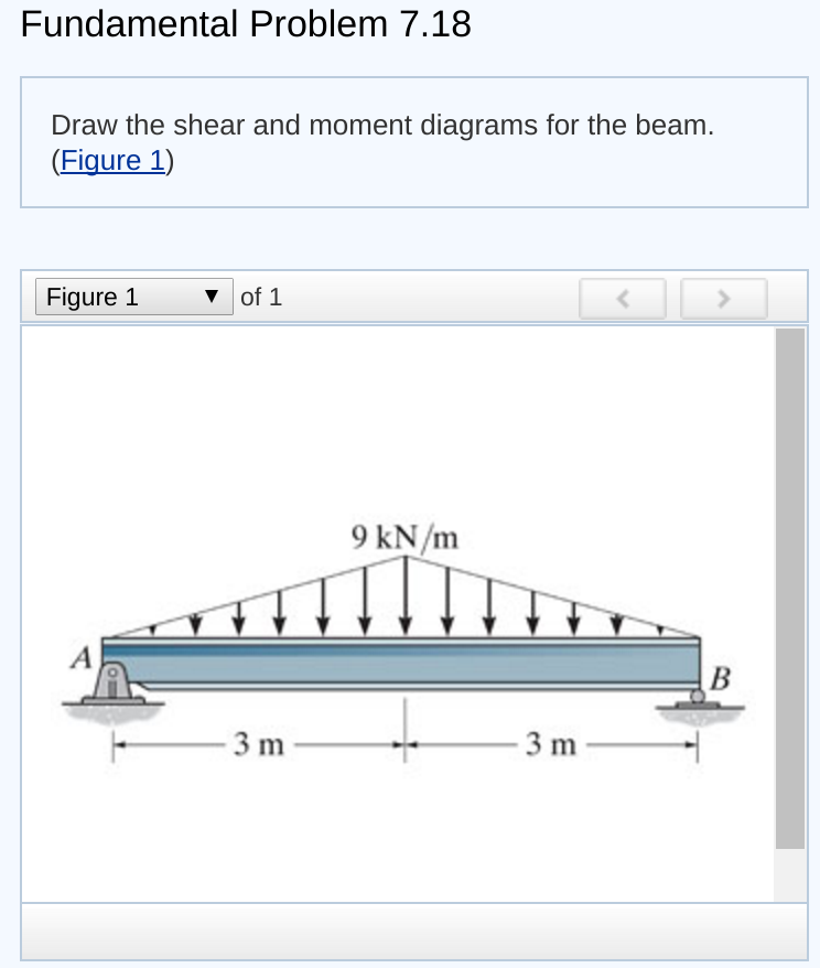
The vertical support reaction at a on. Web the first step in calculating these quantities and their spatial variation consists of constructing shear and bending moment diagrams, \(v(x)\) and \(m(x)\), which are the internal shearing forces and bending moments induced in. Web this problem has been solved! Web step 1 we are given the two loads of 3 kn / knmm and at a distance of 3m each.