
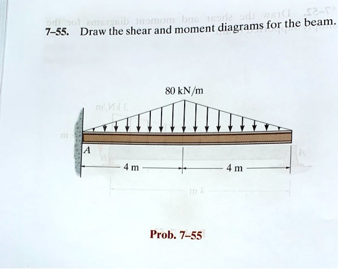
7-55 Draw The Shear And Moment Diagrams For The Beam
7-55 Draw The Shear And Moment Diagrams For The Beam - Draw the shear and moment diagrams for the compound beam. Web shear force and bending moment diagrams are analytical tools used in conjunction with structural analysis to help perform structural design by determining the value of shear forces and bending moments at a given point of a structural element such as a beam. 20 kn, 40 kn/m, 150 knm, 8 m, 3 m. Draw the shear and moment diagrams for the beam. Web shear force and bending moment diagrams are powerful graphical methods that are used to analyze a beam under loading.
You'll get a detailed solution from a subject matter expert that helps you learn core concepts. You'll get a detailed solution from a subject matter expert that helps you learn core concepts. Please establish the shear and moment equations first, and then draw the diagrams) this problem has been solved! You'll get a detailed solution from a subject matter expert that helps you learn core concepts. This problem has been solved! Web shear force and bending moment diagrams are powerful graphical methods that are used to analyze a beam under loading. Draw the shear and moment diagrams for the compound beam.

Solved Draw the shear and moment diagrams for the beam.
Web draw the shear force and bending moment diagrams for the cantilever beam supporting a concentrated load of 5 lb at the free end 3 ft from the wall. Draw the shear and moment diagrams for the beam. 20 kn 40 kn/m cl 150 kn m 8 m 3 m prob. Web the first step.

Learn How To Draw Shear Force And Bending Moment Diagrams Engineering
This page will walk you through what shear forces and bending moments are, why they are useful, the procedure for drawing the diagrams and some other keys aspects as well. Web draw the shear force and bending moment diagrams for the shown beam, and determine the maximum sf and bm this problem has been solved!.
Solved Draw the shear and moment diagrams for the beam
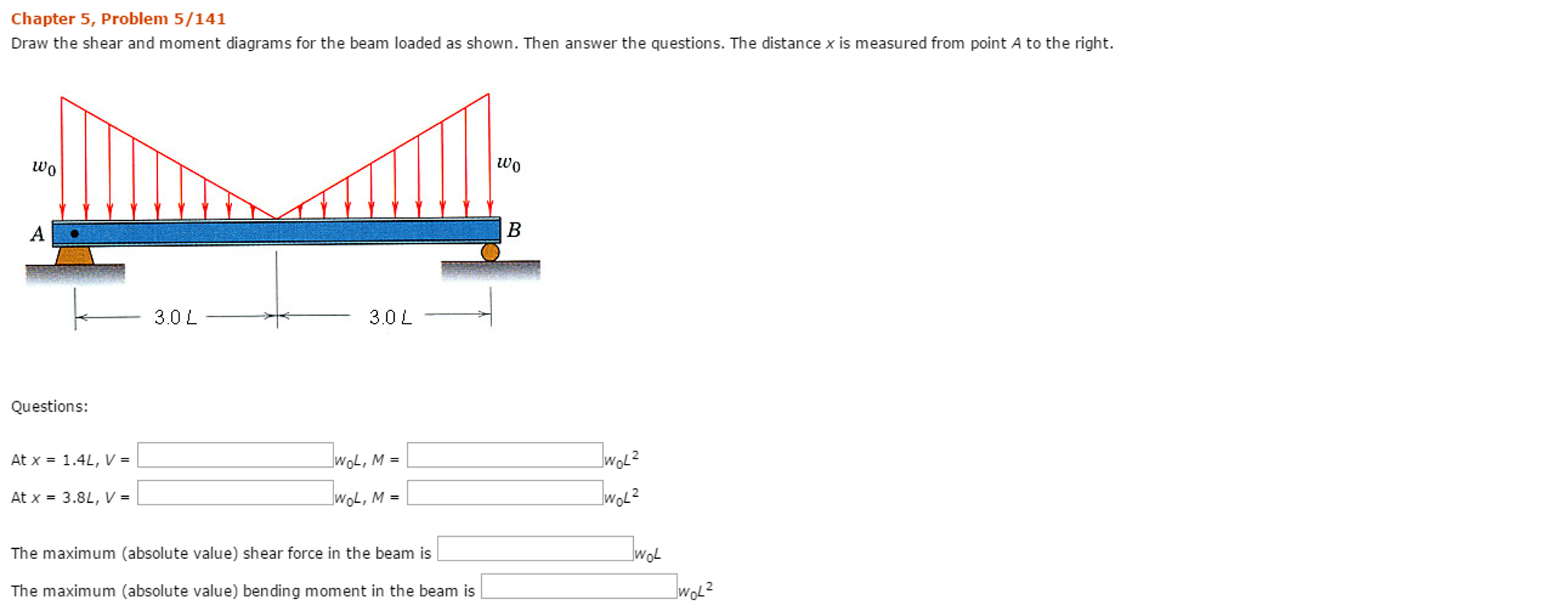
In each problem, let x be the distance measured from left end of the beam. Web shear force and bending moment diagrams are analytical tools used in conjunction with structural analysis to help perform structural design by determining the value of shear forces and bending moments at a given point of a structural element such.
Solved Draw the shear and moment diagrams for the beam.
Also, draw shear and moment diagrams, specifying values at all change of loading positions and at. You'll get a detailed solution from a subject matter expert that helps you learn core concepts. Draw the shear and moment diagrams for the compound beam. Draw the shear and moment diagrams for the beam. Web the first step.
Solved Draw the shear and moment diagrams for the beam.
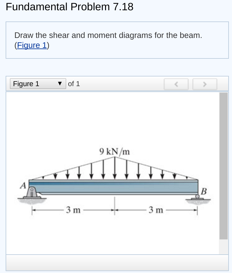
Web draw the shear and moment diagrams for the beam. This problem has been solved! Include in your solution the equations for shear and moment for this beam. Web draw the shear and moment diagrams for the beam. Statics, 14th edition russell c. Don't forget to include x distances where v or m is zero..

Learn How To Draw Shear Force And Bending Moment Diagrams Engineering
Draw the shear and moment diagrams for the compound beam. Unfortunately it’s probably the one structural analysis skill most students struggle with most. The following sections will describe how these diagrams are made. Web draw the shear force and bending moment diagrams for the shown beam, and determine the maximum sf and bm this problem.

Solved Draw the shear and moment diagrams for the beam, and
Don't forget to include x distances where v or m is zero. Web shear force and bending moment diagrams are analytical tools used in conjunction with structural analysis to help perform structural design by determining the value of shear forces and bending moments at a given point of a structural element such as a beam..

Draw the shear and moment diagrams for the beam.
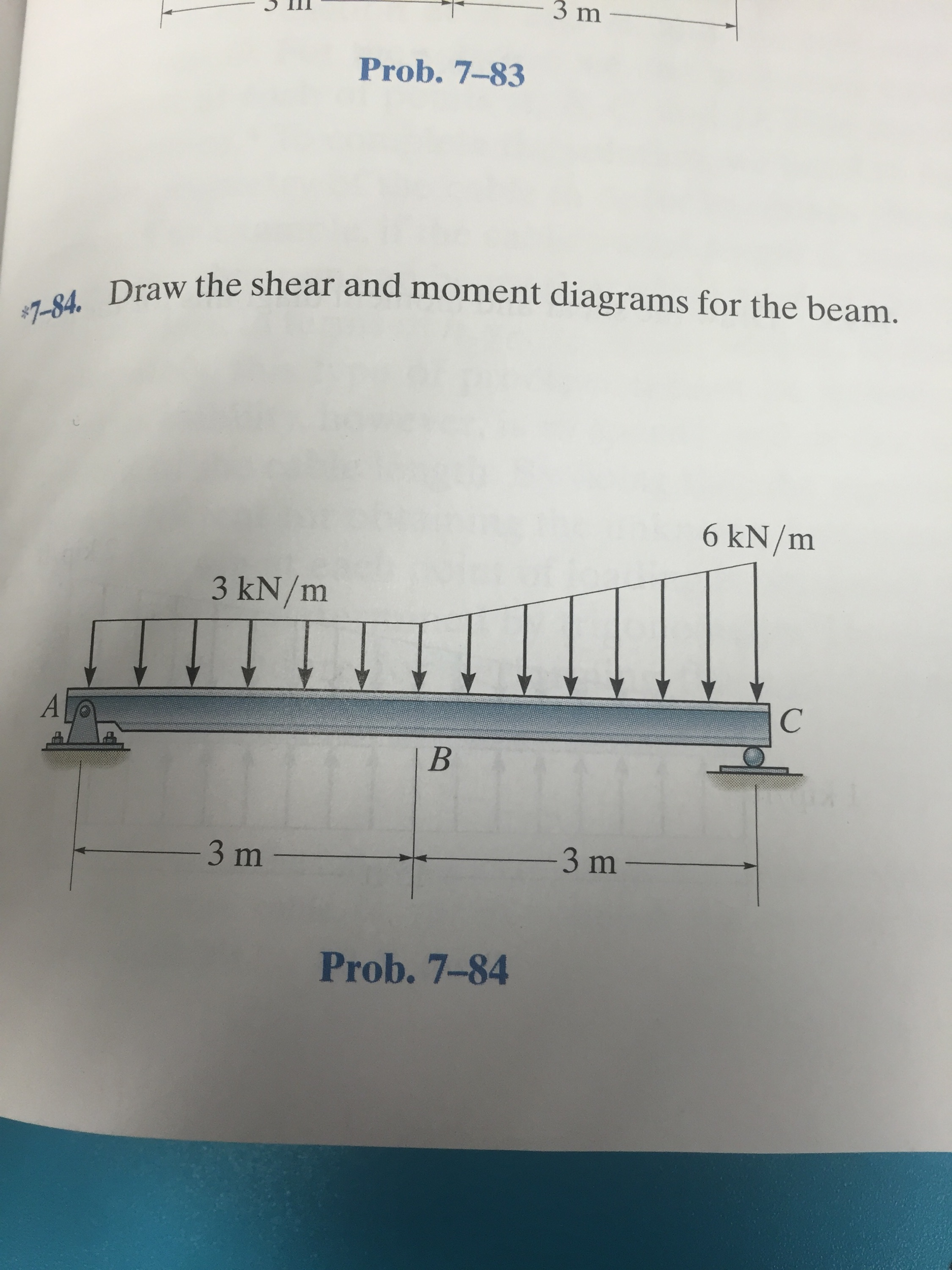
W a с b 를 l prob. Don't forget to include x distances where v or m is zero. Statics, 14th edition russell c. Draw a fbd of the structure. * hint, you will need different equations for portions ab and bc of this beam. 20 kn 40 kn/m cl 150 kn m 8 m.

Drawing Shear and Moment Diagrams for Beam YouTube
* hint, you will need different equations for portions ab and bc of this beam. You will need different equations for portions ab and bc of this beam. The following sections will describe how these diagrams are made. Ft b 10 ft 20 ft 10 ft prob. Web write shear and moment equations for the.
Draw The Shear Diagram For Beam 7 55 The Best Picture Of Beam
Web this video explains how to draw shear force diagram and bending moment diagram with easy steps for a simply supported beam loaded with a concentrated load. Draw the shear and moment diagrams for the beam. Draw the shear and moment diagrams for the beam. You will need different equations for portions ab and bc.
7-55 Draw The Shear And Moment Diagrams For The Beam Web our calculator generates the reactions, shear force diagrams (sfd), bending moment diagrams (bmd), deflection, and stress of a cantilever beam or simply supported beam. Draw the shear and moment diagrams for the beam. Web shear force and bending moment diagrams are powerful graphical methods that are used to analyze a beam under loading. Draw the shear and moment diagrams for the beam. Don't forget to include x distances where v or m is zero.
Web The First Step In Calculating These Quantities And Their Spatial Variation Consists Of Constructing Shear And Bending Moment Diagrams, \(V(X)\) And \(M(X)\), Which Are The Internal Shearing Forces And Bending Moments Induced In The Beam, Plotted Along The Beam's Length.
20 kn, 40 kn/m, 150 knm, 8 m, 3 m. Skyciv beam tool guides users along a professional beam calculation workflow, culminating in the ability to view and determine if they comply with your region's design codes. Hibbeler thank you guys for watching. Include in your solution the equations for shear and moment for this beam.
Web Shear Force And Bending Moment Diagrams Are Analytical Tools Used In Conjunction With Structural Analysis To Help Perform Structural Design By Determining The Value Of Shear Forces And Bending Moments At A Given Point Of A Structural Element Such As A Beam.
Unfortunately it’s probably the one structural analysis skill most students struggle with most. The following sections will describe how these diagrams are made. You'll get a detailed solution from a subject matter expert that helps you learn core concepts. Statics, 14th edition russell c.
This Page Will Walk You Through What Shear Forces And Bending Moments Are, Why They Are Useful, The Procedure For Drawing The Diagrams And Some Other Keys Aspects As Well.
Web to draw shear and moment diagrams for a beam, one must first determine the reactions and the values of the forces acting on the beam. Web this video explains how to draw shear force diagram and bending moment diagram with easy steps for a simply supported beam loaded with a concentrated load. Web draw the shear and moment diagrams for the beam. Draw a fbd of the structure.
* Hint, You Will Need Different Equations For Portions Ab And Bc Of This Beam.
20 kn 40 kn/m в. Web our calculator generates the reactions, shear force diagrams (sfd), bending moment diagrams (bmd), deflection, and stress of a cantilever beam or simply supported beam. Web draw the shear force and bending moment diagrams for the cantilever beam supporting a concentrated load of 5 lb at the free end 3 ft from the wall. Web figures 1 through 32 provide a series of shear and moment diagrams with accompanying formulas for design of beams under various static loading conditions.