
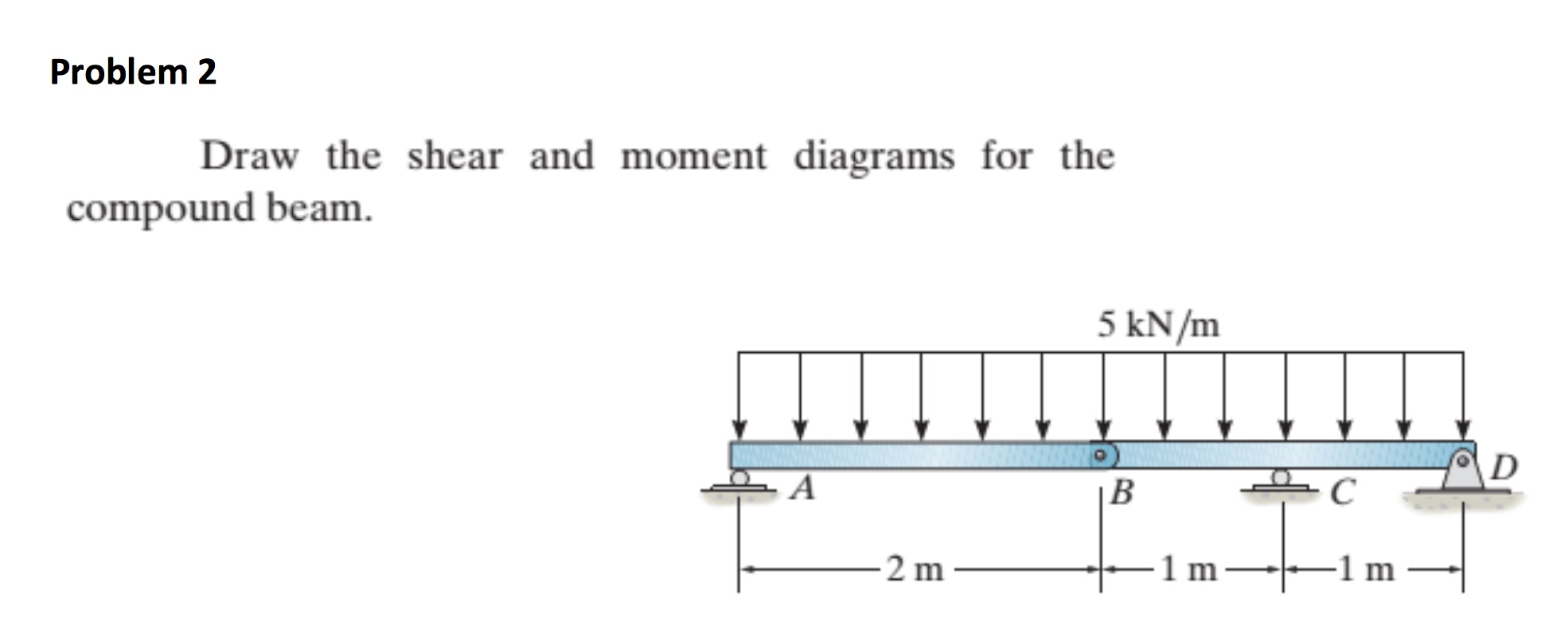
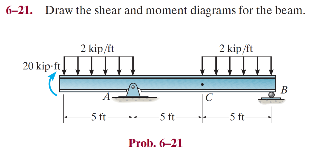
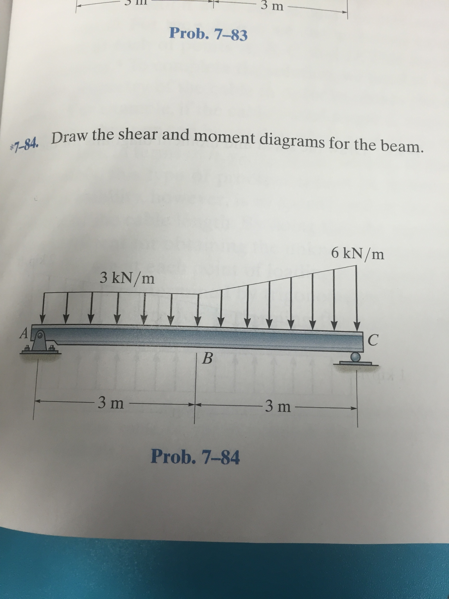
6-21 Draw The Shear And Moment Diagrams For The Beam
6-21 Draw The Shear And Moment Diagrams For The Beam - Draw the shear and bending moment diagrams for the beam. Web draw the shear and moment diagrams for the simply supported beam. Draw the shear and moment diagrams for the beam and determine the shear and moment in the beam as functions of x, where 4 ft < x < 10 ft. 200 lb ft b x 4 ft 4 ft 150 lb/ft 6 ft 200 lb ft a ans. Skyciv beam tool guides users along a professional beam calculation workflow, culminating in the ability to view and determine if they comply with your region's design codes.
By drawing the free body diagram you identify all of these loads and show then on a sketch. In general the process goes like. Use both the mathematical convention and the engineering convention for the bending moment diagram. Web step 1 | draw a free body diagram. Web draw the shear and moment diagrams for the beam. You'll get a detailed solution from a subject matter expert that helps you learn core concepts. Web our calculator generates the reactions, shear force diagrams (sfd), bending moment diagrams (bmd), deflection, and stress of a cantilever beam or simply supported beam.
draw the shear and moment diagrams for the beam chegg
Web our calculator generates the reactions, shear force diagrams (sfd), bending moment diagrams (bmd), deflection, and stress of a cantilever beam or simply supported beam. Skyciv beam tool guides users along a professional beam calculation workflow, culminating in the ability to view and determine if they comply with your region's design codes. Use both the.

Solved Draw the shear and moment diagrams for the beam, and
Web step 1 | draw a free body diagram. Web introduction figures 1 through 32 provide a series of shear and moment diagrams with accompanying formulas for design of beams under various static loading conditions. In general the process goes like. Web shear/moment diagrams are graphical representations of the internal shear force and bending moment.

Brief Information About Shear Force And Bending Moment Diagrams
You'll get a detailed solution from a subject matter expert that helps you learn core concepts. Web introduction figures 1 through 32 provide a series of shear and moment diagrams with accompanying formulas for design of beams under various static loading conditions. Web the first step in calculating these quantities and their spatial variation consists.
Solved 621. Draw the shear and moment diagrams for the beam
To correctly determine the shear forces and bending moments along a beam we need to know all of the loads acting on it, which includes external loads and reaction loads at supports. Web write equations for the shear v and bending moment m for any section of the beam in the interval ab. Skyciv beam.

Solved Draw the shear and moment diagrams for the beam.
Web introduction figures 1 through 32 provide a series of shear and moment diagrams with accompanying formulas for design of beams under various static loading conditions. Web the first step in calculating these quantities and their spatial variation consists of constructing shear and bending moment diagrams, \(v(x)\) and \(m(x)\), which are the internal shearing forces.
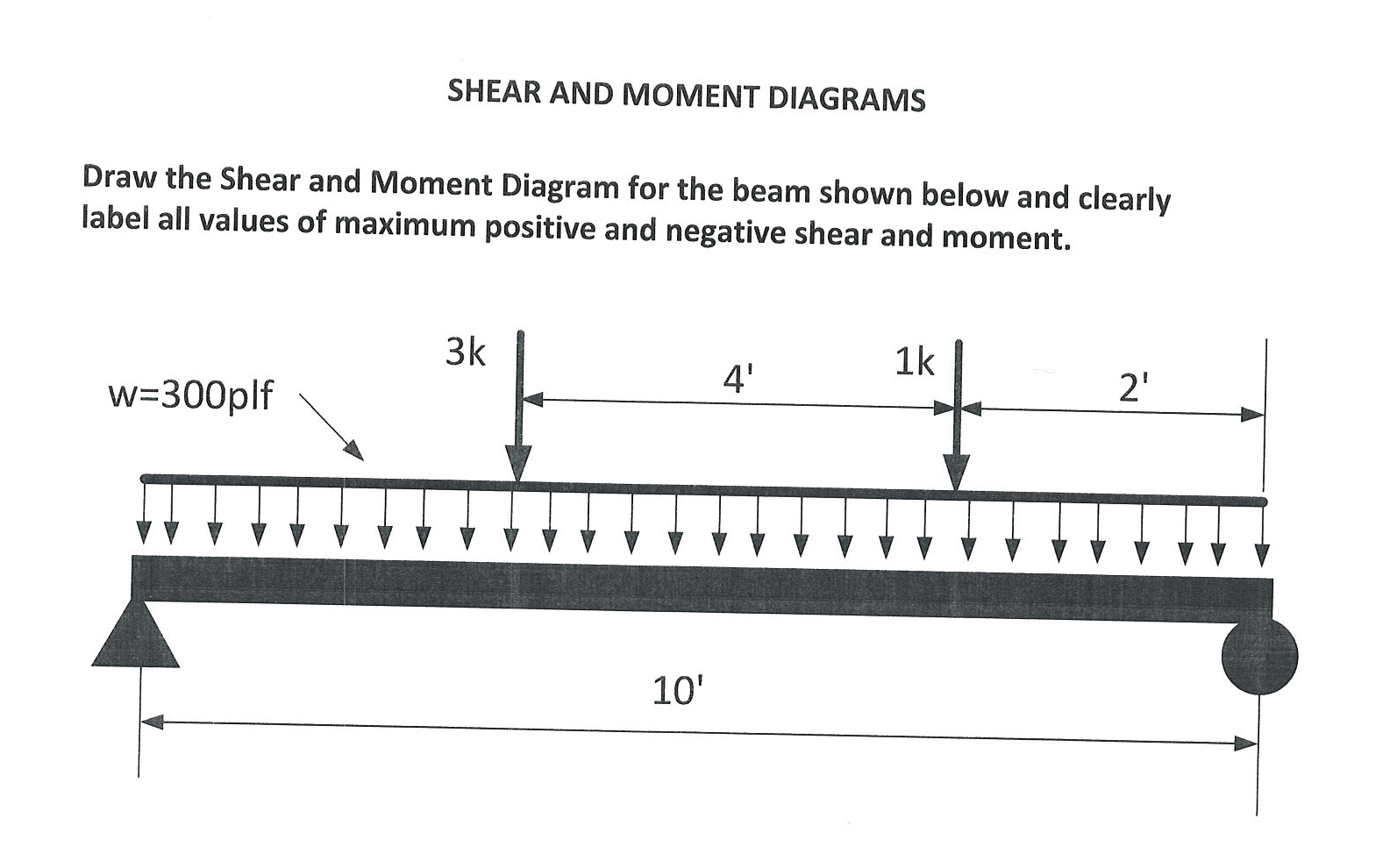
Solved Draw the Shear and Moment Diagram for the beam shown
Skyciv beam tool guides users along a professional beam calculation workflow, culminating in the ability to view and determine if they comply with your region's design codes. This is an example problem that will show you how to graphically draw a shear and moment diagram for a beam. Unfortunately it’s probably the one structural analysis.

Drawing Shear and Moment Diagrams for Beam YouTube
Write shear and moment equations for the beams in the following problems. Andrew pytel and jaan kiusalaas publisher: Shear and moment diagrams and formulas are excerpted from the western woods use book, 4th edition, and are provided herein as a courtesy of western wood. Web step 1 | draw a free body diagram. In general.

Learn How To Draw Shear Force And Bending Moment Diagrams Engineering
Firstly calculating reactions at support. The beam will fail when the maximum moment Web to design a beam, it is essential to determine the maximum shear and moment in the structure. Web a diagram showing the variation of the shear force along a beam is called the shear force diagram. Consider a section bc and.
Solved Draw the shear and moment diagrams for the beam.
The bending moment at a section of a beam can be determined by summing up the moment. Draw the shear and moment diagrams for the beam. You'll get a detailed solution from a subject matter expert that helps you learn core concepts. One of the ways to do this is through the use of shear.
Solved Draw the shear and moment diagrams for the beam
You'll get a detailed solution from a subject matter expert that helps you learn core concepts. The vertical support reaction at a on. By drawing the free body diagram you identify all of these loads and show then on a sketch. In the questions the location x proceeds from left to right! Web our calculator.
6-21 Draw The Shear And Moment Diagrams For The Beam In each problem, let x be the distance measured from left end of the beam. Web the first step in calculating these quantities and their spatial variation consists of constructing shear and bending moment diagrams, \(v(x)\) and \(m(x)\), which are the internal shearing forces and bending moments induced in. In general the process goes like. Statics, 4th edition 4th edition isbn: 23rd july 2021 | tutorial in this post we’re going to take a look at shear and moment diagrams in detail.
Skyciv Beam Tool Guides Users Along A Professional Beam Calculation Workflow, Culminating In The Ability To View And Determine If They Comply With Your Region's Design Codes.
Web draw the shear and moment diagrams for the beam. Web a diagram showing the variation of the shear force along a beam is called the shear force diagram. Firstly calculating reactions at support. The vertical support reaction at a on.
Web Draw The Shear And Moment Diagrams For The Simply Supported Beam.
Consider a section bc and at a distance x from point a. The total load on the beam r a + r b = 2 × 5 + 2 × 5 = 20 k i p. In the questions the location x proceeds from left to right! Draw the shear and moment diagrams for the beam, and determine the shear and moment in the beam as functions of x for 0 x 4 ft, 4 ft x 10 ft, and 10 ft x 14 ft 250 lb 250 lb 150 lb/ft 6 ft 4 ft 4 ft prob.
Web Draw The Shear And Moment Diagrams For The Beam.
Shear and moment diagrams and formulas are excerpted from the western woods use book, 4th edition, and are provided herein as a courtesy of western wood. Web to design a beam, it is essential to determine the maximum shear and moment in the structure. We are asked the shear and bending moment diagrams for the beam. Use both the mathematical convention and the engineering convention for the bending moment diagram.
The Reactions Shown On The Diagram Are Determined From Equilibrium Equations As.
Also, draw shear and moment diagrams, specifying values at all change of loading positions and at points of zero shear. In each problem, let x be the distance measured from left end of the beam. Draw the shear and moment diagrams for the beam. Web write equations for the shear v and bending moment m for any section of the beam in the interval ab.